
Left Coast Resident
Ubẽr Clubbie
How to: Lift Pump Fail Safe Fuel Circuit
Introduction:
I’ve posted up about this before in a random manner. In two parts, here is all the information, part numbers, and procedures together with pictures. Other threads detail the ‘how to’ and the ‘why of’ installing the PD pump in an ALH car, and won’t be gone into here. Use the advanced search function to find threads with the words ‘lift pump’ in their titles.
Note: This isn’t meant for PD cars, as I don’t know if the PD IP will pull a vacuum at its inlet.
History:
With your fuel filter in good condition, the VE pump will pull approximately 8 to 10” Hg. (negative 4-5 lbs.) suction at its inlet. The PD pump will give you 5-7 lbs. at idle, a difference of 9 to 12 lbs., or thereabouts. But the PD pump is a positive displacement pump and if it stops running for whatever reason, NO fuel can be drawn through it, and your engine stops running. Opps! The solution is to ‘T’ in a second fuel pick-up line with a check valve in it. Under pressure when the pump is running the check valve closes. If the pump stops working with the engine running or attempting to run, the check valve opens and the fuel flows to the IP as it would have in its stock configuration.
Materials:
I sourced materials to be compatible with diesel and bio-diesel, and to be OK to 190º F min. I doubt you’ll see temperatures as high as I’ve allowed for.
The following materials ARE NOT suitable (or particularly suitable) for bio-diesel: brass, bronze, copper, lead, tin, zinc, ethylene polypropylene (EPDM), hypalon, hysunite rubber (Goodyear brand name), neoprene, nitrile (aka Buna-N), non-fluorinated rubber, polyethylene (HDPE), polypropylene, PVC, silicone, tygon, vinyl, polyvinyl.
The following materials ARE suitable (or pretty much suitable) for bio-diesel: acetal (POM) copolymer (watch out for a high enough temperature rating), aluminum, steel, fluorinated polyethylene, fluorinated polypropylene, teflon, fluorosilicone, kynar, nylon (temp range varies from 200º F to 270º F -- if you don’t know, assume the lowest temp rating), polyurethane (watch out for low temp rating – max temp will be 165º F to 180º F – if you don’t know, assume the lowest temp rating), viton, viton B (fluoroelastomer aka FKM).
What you are doing:
You’re just ‘Tee’ing in a 2nd line with a check valve in between the pump outlet tube and the barb it goes to on the underside of the top of the fuel assembly. The end of your new line just goes down into the bottom of the well assembly so that it's always in a supply of fuel. So much for the simplicity of it – let me give you a walk through.
Parts and where you get them:
Here are the parts you need, they come more or less from two sources – McMaster Carr, and Cole Parmer Co., and yes I know that the barbs in the pump are 5/16”, but bear with me, please. If you have other sources, post it up here, or PM me and I'll add them:
Tubing – 2 feet of thin wall (3/8” OD, 1/4” ID, 1/16” thick) ‘firm’ Viton tubing, part #5119 K861 from McMaster Carr . Click on the link, then type in ‘Viton tubing’; you’ll find it. I chose green so that when I find pieces later in my garage I'll recall that I am looking at Viton and not some incompatible grade of rubber as listed above. You won’t need the full 2’ – but DON’T order too little. For one thing, if you look the pictures of the completed modification, you'll see that the line can not loop too tightly, or it will kink. I didn’t buy it from Cole Parmer because they don’t sell it in short lengths.
Check valve – this has a nylon body with a fluorosilicone diaphragm, and is 1/4" barb – it is also available from McMaster Carr , part #47245K27. FWIW, you can also get it at Cole-Parmer: part #EW-98553-02, Nylon Check Valve, 1/4" ID.
'T' fitting, nylon – 1/4” x 1/4” x 1/4”. After buying a 10 pack of 5/16” x ¼” reducing ‘T’s from Cole-Parmer, I discovered that a straight 1/4" 'T' fitting was shorter in overall length, and would work better. I think McMaster Carr has them, but I’m not sure and couldn’t find a receipt for them. On their website, search pages 136 thru 139 for a starting point. Warning, warning, warning: 1) I like multi-barb better than single barb because they provide more friction and because as you will see below, I cut them shorter to fit the space limitations. 2) You want nylon for temperature and compatibility reasons. DON’T buy common polyethylene or polypropylene fittings that are easily available. You'll regret it.
Here is a photo of the three parts you need:

Check valve, 'T' fitting, random lengths of Viton tubing I had laying around.
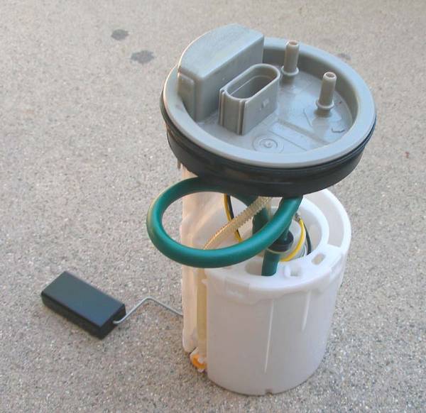
Crazy Dave’s (DOK to you) stock PD pump that we previously installed in his 2001 ALH:

You’ll see two yellowish convoluted lines, the bigger is the line out of the pump, and the one we’ll have to replace (as you can’t just cut it and ‘T’ into it). It appears to be acetal copolymer. That’s not real important to you – I just like using big words that I don’t completely understand. The small line is the pick-up line that feeds the pump.
Lay the lift pump down on your workbench and remove the 4 Torx screws so that you can gain better access to the Oetiker clamps on the fuel line that you’re going to remove.

The two halves are apart and I’m prying open one of the Oetiker clamps so that I can pull it off.

Lift pump tools of death and destruction with the two destroyed Oetiker clamps.

From top to bottom, left to right: long nose pliers, long nose pliers, screwdriver, nail pulling pliers, screwdriver, and 2 dead Oetiker clamps. The nail pulling pliers killed the top Oetiker clamp (the one you can get to – you’ll see when you do it) in literally seconds – a trick I learned from the guys at the local hydraulic shop.
Here you see one end of the fuel line. It will slice easily with your sharp Exacto knife.

3 to 5 gentle slices lengthwise towards the barb and in a few more seconds you’ll have it tweaked off.
A gratuitous photo of the two parts of the pump separated. I’m about to attack the remaining Oetiker clamp.

Here I am cutting the barbed 1 /4” nylon ‘T’ I’ll be using.

For your dining and dancing pleasure, here’s the ‘T’ partially cut to illustrate what I’m up to.

The other two legs are cut in the same manner before it is used.
Continued . . .
Last edited:


") Brilliant.
Brilliant.