ALH TDI engine transplant into '84 Vanagon

AndyBees

Top Post Dawg
Joined
May 27, 2003
Location
Southeast Kentucky
TDI
Silver 2003 Jetta TDI, Silver 2000 Jetta TDI (sold), '84 Vanagon with '02 ALH engine
Update

I received the wiring cables today. I installed two runs of cable containing 15 wires of 22 gauage and one run of cable containing 9 wires of 18 gauge.

I will use 27 of the 30 22 gauge wires to handle the accelerator, OBD, Cruise Control and a few other things.

The 9 18 gauge wires will take care of the Clutch and Brake Switch circuits and positve for the VSS.

I installed a flexible 3/4 inch conduit and was able to get all three cables inside.

I did not make any connections. Sorry, no photos either!

This will be my last update for at least a week .................. few days vacation in the national capital (DC).
 

jjordan11

Veteran Member
Joined
Jan 5, 2008
Location
Lehi, UT
TDI
1988 Audi 80 quattro PD130, 1982 Westfalia TDI
Andy I really like the cruise control stalk, you have to be one of the most talented artists with the application of JB Weld:D. I too have thought about doing my cruise the same way as Joao, but after seeing yours I might. E tempted to follow your lead. Keep up the good work.

Mark, your new routing looks good too. I am a bit envious of the work going on with your vanagons, soon I hope to be able to get back on my projects and be finished with house projects.

Jon
 

jackbombay

Top Post Dawg
Joined
Mar 12, 2002
Location
Diesel knows best
TDI
A4 Jetta
Your electrical work looks well done!

I put a tiny button for the cruise in the end of the vanagon stalk,


The wiring just runs up the back of the stalk,


AndyBees

Top Post Dawg
Joined
May 27, 2003
Location
Southeast Kentucky
TDI
Silver 2003 Jetta TDI, Silver 2000 Jetta TDI (sold), '84 Vanagon with '02 ALH engine
Well, it's looking like a great day to travel.................
I-75 North
I-64 East
I-81 North
I-66 East to Crystal City!

Maybe I'll see a TDI along the way, or even a TDI powered Vanagon....or some other TDI conversion!

I like the Cruise idea Jackbombay. I have an extra TDI stalk and Vanagon stalk to work with on my next project (or divorce....LOL). No! Really my wife is looking forward to a long road trip in the Conversion Project this summer.................maybe in time to swing by Ypsilanti, MI for the TDI Fest Labor Day weekend! That would be nice!
 

AndyBees

Top Post Dawg
Joined
May 27, 2003
Location
Southeast Kentucky
TDI
Silver 2003 Jetta TDI, Silver 2000 Jetta TDI (sold), '84 Vanagon with '02 ALH engine
Update

Since the last update, I have installed the "conduit" for the cables. It extends from under the back seat on the left side of the rear heater, down under the van body up to and thru the rubber grommet next to the heater hoses below the front dash.

As I stated in the last update, I was able to install inside the 3/4 inch flexible conduit two cables containing 15 wires of 22 gauge and one cable containing 9 wires of 18 gauge.

After going over the wiring schematics, it appears that I will be using all but one of those wires.

Here are a few shots of what it is looking like, front to rear of vehicle. (all comments are at top of photos)

This is pic of the conduit with cables just below the dash of the Vanagon.


This pic is just below where the conduit comes out in the cabin at the dash (previous photo). As those who know, the conduit here is just to the left of the gear shifter box of the Vanagon.:D


This pic is from an angle a little farther back. You are still looking toward the front of the vehicle and the gear shifter box can be seen there in the background on the right. Notice that the support is a segment of Serpentine belt secured with two stainless steel screws.;)


This pic is a little farther back looking from the right side of the vechicle. The gear shifter tube can be seen with the new center bushing. Also, another securing strap can be seen. Also, in the pic below, if you look at the upper left corner you can see a metal strap hanging there. Well, to put things into perspective, that strap holds the cross-over vent pipe on top of the fuel tank. When the fuel tank is re-installed this section will not be visible from below or anyother angle..........those that know Vanagons, knows!:D


This pic shows the conduit with sweep elbow at the point it goes up and under the back seat on the left side of the back heater. It will have a securing strap attached later.


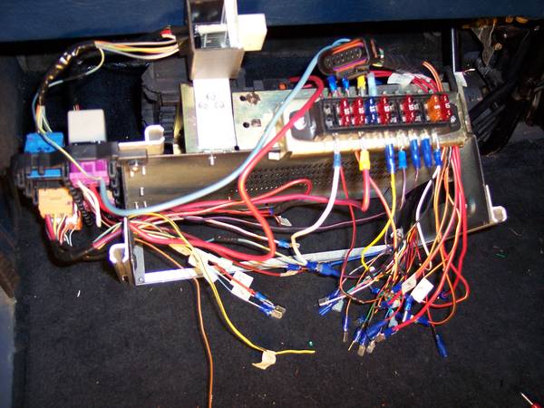
This pic shows the three cable bundles laying across the rear heater extending over to where the ECU and fuse panels will be located. See previous posts and photos relating to this area and the ECU. Yeah, that heater assembly needs a good cleaning!


In this last pic, you can see the area where the ECU and fuse panels will be sitting. The wiring harnesses have been temporarily removed. The large access hole and two holes for the coolant pipes to the heater can be seen as well.


Also, as I stated above the last photo, I removed the two wiring harnesses for some additional custom modifications. I shortened the GP circuit by about 8 inches. I tape warped the custom wire bundle containing circuits for the PCV heater, coolant level sensor and MAF sensor. I used some liquid electrical tape to seal all the "branches" to protect the wiring from water. Everything has been wrapped in good electrical tape. However, I wanted the added protection of the liquid tape, especially at those branches.
 
Last edited:

jjordan11

Veteran Member
Joined
Jan 5, 2008
Location
Lehi, UT
TDI
1988 Audi 80 quattro PD130, 1982 Westfalia TDI
I also really like the conduit running to the front, I just have the cable running by itself. I think I'll have to change mine when I can get back to it.
 

jackbombay

Top Post Dawg
Joined
Mar 12, 2002
Location
Diesel knows best
TDI
A4 Jetta
I also really like the conduit running to the front, I just have the cable running by itself. I think I'll have to change mine when I can get back to it.
That is a big job if the wiring is already hooked up, for mine "after the fact" wiring protection I bought 1" inner diameter clear vinyl tubing and cut it the entire length down one side then slipped it over my wiring and zip tied it closed every 6" or so.


The conduit set-up is the cat's pajamas's!
 

AndyBees

Top Post Dawg
Joined
May 27, 2003
Location
Southeast Kentucky
TDI
Silver 2003 Jetta TDI, Silver 2000 Jetta TDI (sold), '84 Vanagon with '02 ALH engine
Update

Wow, two updates in one weekend.

This evening (after the game UK Wildcats/Baylor), I went over the Vanagon wiring schematic on-site at the dash. My goal was to identify the Vanagon circuits for the "hi-beam" head light indicator and the two circuits for the right and left signal lights. (For those who know Vanagons, know that there is only one indicator light in the cluster to show that "a" signal is on.) Those will be spliced into the TDI wiring circuits going to the Custom TDI cluster to indicate right or left signal and emergency flasher. Although on paper it looked fairly easy, actually confirming everything was a bit of a challenge!

I also adjusted the length of the wire cables at the front of the Van (see previous post(s) for details). I'm not exactly ready to cut them to length just yet!

More later!
 

AndyBees

Top Post Dawg
Joined
May 27, 2003
Location
Southeast Kentucky
TDI
Silver 2003 Jetta TDI, Silver 2000 Jetta TDI (sold), '84 Vanagon with '02 ALH engine
Update
After two and half days away from the project, I was very excited to get back in the garage this afternoon.

So, I finished labeling all the wires to be used in the three cables. Although everything is identified in my schematics, wire color and pattern is different with the cables. Therefore, identity becomes very important.........don't want to fry anything when I turn on the key.

#1 Cable, all 15 circuits of the cable, which involve the Accelerator, Cruise Control and four miscellaneous circuits will be used (22 gauge)
#2 Cable, using 13 circuits of 15 (22 gauge)
#3 Cable, using all nine circuits that primarily address the brake and clutch switches (18 gauge)

Besides the accelerator, cruise control and brake & clutch switches, the circuits of the right and left (Blue and Green) of the Jetta Cluster are coming into play now. I'll be using 20 of 32 circuits on the Blue side and 9 circuits of 32 on the Green side of the Cluster. The other circuits either don't exist or do not apply to my application. Those circuits that do not apply are labeled in case I need to deal with a "light" or warning, such as ABS, etc.
 

AndyBees

Top Post Dawg
Joined
May 27, 2003
Location
Southeast Kentucky
TDI
Silver 2003 Jetta TDI, Silver 2000 Jetta TDI (sold), '84 Vanagon with '02 ALH engine
1st April update

Update

Well, I have continued to work with the wiring under the back seat and at the dash over the last week. As the wiring task moves along, I'm beginning to feel better about how it is all falling in place. If everything goes well, I should be able to turn ON the key and check things out with VAG COM in about a week.

I did remove all the wiring from the engine again. Two reasons: I do have to either drop the tranny or remove the engine to install the flywheel and clutch (That's old information, but adds to the chores still ahead.). Second, I did re-wrap a few branch circuits for ease of management and finished some splices.

Here a few photos of the latest developments. (Comments are at the top of each photo.)

This is a shot of the 14-pin connector from the Fan Control Module that I am using. It has been posted previously. Here it is ready to accept the solder. EDIT: 1/20/20, I did not use the Fan Control Module 14-pin connector. That was a bad plan. So, I used two or three smaller connectors. I did explain this by editing previous posts.


This is Cable #1 consisting of 15 22 gauge wires that will be soldered to the 14-pin connector


In this photo the wires have been soldered on. You can see there are a group of 4 and 2 circuits that will not go thru the 14-pin connector. Although the wires are labeled, I have a master list to keep track of each circuit and it's purpose(s).


In this photo, you are looking at the "wiring central" at the back seat (as seen in previous posts). Here the many circuits are being preped for proper length and to receive connectors.


This is a similar photo as the previous one. Notice that most of the circuits have the single plug connectors crimped on. Yes, there is a better way to do. I do have enough "slack" to come back some time in the future with multi pin connectors for grouping.


The next three photos are up front below the dash. These are primarily the Accelerator and Cruise Control circuits. All these have been finished and ready for wraping in tape and grouping for final placement.


This photo is similar to the one above


This update will be continued in the next Post!
 
Last edited:

AndyBees

Top Post Dawg
Joined
May 27, 2003
Location
Southeast Kentucky
TDI
Silver 2003 Jetta TDI, Silver 2000 Jetta TDI (sold), '84 Vanagon with '02 ALH engine
Here is what I consider a major accomplishment with locating the OBD port and TDI ignition assembly. The OBD port in the photo below is located on the lower part of the dash just to the right of the Vanagon steering column. Notice the space just above the port location.


Another view of the OBD port with the cover inserted.


Here is a shot showing the TDI ignition just above the OBD port


This shot is with the ignition key in place and the OBD port cover inserted.


This shot is looking inside the dash thru the area where the Cluster will be sitting. You are looking at the support I fabricated to secure the TDI ignition in place.


This shot is zoomed out just a little


This shot is zoomed out farther. You can see the aluminum bracket I fabricated to hold the TDI ignition assembly in position. There is ample space behind for the electrical connector to be plugged on.


This is how the TDI ignition will work. The key must be in the ON position. Then the Vanagon ignition is turned on and to "start." Either key will kill the engine. But, the TDI electrical management system is made "hot" when the Vanagon key is turned ON......make sense?
 
Last edited:

rackaracka

Veteran Member
Joined
Nov 15, 2001
Location
Monroe, NJ
Andy, pardon my ignorance, but why do you have to have two ignitions? I would think you could have just used the vanagon one. That being said, it looks really great where you put it. Great job.
 

AndyBees

Top Post Dawg
Joined
May 27, 2003
Location
Southeast Kentucky
TDI
Silver 2003 Jetta TDI, Silver 2000 Jetta TDI (sold), '84 Vanagon with '02 ALH engine
Two ignitions

Andy, pardon my ignorance, but why do you have to have two ignitions? I would think you could have just used the vanagon one. That being said, it looks really great where you put it. Great job.
Well, it has the immobilizer which requires the use of the key. I know that the immobilizer can be deleted. However, early on in this project not being familiar with that procedure, I wasn't sure what else would be deleted. I did not bother to look into the results of such a procedure.

So, considering that I am using the TDI cluster, I want to use as many of the sensors as possible, such as fuel level, windshield washer level, door ajar, key in ignition, coolant level, etc.

Lastly, back early on in this Thread, I discussed the use of the second ignition for theft purposes. As I directed Jon Jordon, go to the Samba.com and look at the postings of stolen VWs! ....you might be suprised.

As I stated in the last post, when the Vanagon ignition is turned to the ON position that makes the TDI ignition hot. However, for the TDI engine systems to be functional, that ignition must be turned to the ON position also. Either one will kill the engine by turning OFF.

One more, I do have another "system" that will add to the security of the vehicle:D
 

markward

Veteran Member
Joined
Jul 5, 2007
Location
Loxahatchee, Florida
TDI
82 Vanagon and 2011 JSW
Andy, good progress. One note, my engine would not shut off by turning the key off. Turned out to be the alternator was backfeeding power to the ignition switch probably through the warning light circuit. The fix was to add a diode I purchased from radio shack and installed it inline with the terminal 15 on the vanagon switch. Problem solved. mark
 

AndyBees

Top Post Dawg
Joined
May 27, 2003
Location
Southeast Kentucky
TDI
Silver 2003 Jetta TDI, Silver 2000 Jetta TDI (sold), '84 Vanagon with '02 ALH engine
Easter weekend up date

Here are a few pics reflecting the installation of another conduit for additional circuits.

These pics show the 1/2 inch OD plastic conduit. It contains eight wires pertaining to the rear located OBD port, fuel tank level sensor, windshield washer level sensor and one power wire for the Intercooler Fan.

All comments are at the top of each photo!

Here is an up front below the dash pic. The other conduit is there in the background


Here, you are looking up behind the Radiator......fan motor is visible, as well as the other conduit.


In this pic, you can see the two circuits coming out of the side of the conduit. Those circuits go to the windshield washer fluid level sensor. The sensor is from a TDI Jetta and will be tied into the cluster. The area where the circuits come out of the conduit will be injected with silicone sealer!


In this pic, you can see the windshield washer pump and sensor level connector. There will be an almost new washer tank installed (good junk yard find). Also, for those who know Vanagons, the TDI washer pump motor will fit in the same slot as with that 24 year old pump!


In this pic, you can see the two circuits for the fuel level sensor. I will also seal that hole with silicone sealer. EDIT: 1/20/19, pic below, although I did use these two circuits for the fuel level sensor (posted very early in this Thread), I later removed the connector and cut away the plastic on the receptacle. I soldered two wires with long pig-tails to the receptacle contacts and covered with JB Weld. The reason is because the connector and receptacle were to high on top of the fuel tank and were mashed up against the bottom of the Van.


In this pic, you can see the smaller conduit going up by the larger conduit. They come out on the left side of the rear heater under the back seat!


The clear plastic tube has not been secured as of yet.

Yes, I will have two OBD ports, one up front and one in the engine bay! I purchased a used port for a gasser vehicle. It was a simple procedure to re-arrange the circuits for the TDI use. I also had to add one circuit. Yes, they are different.
 
Last edited:

AndyBees

Top Post Dawg
Joined
May 27, 2003
Location
Southeast Kentucky
TDI
Silver 2003 Jetta TDI, Silver 2000 Jetta TDI (sold), '84 Vanagon with '02 ALH engine
Update:

Well, not much but some progress.

This afternoon was the first time I've had an opportunity to work on the project since Saturday.

Gees! I almost went brain dead looking at all those circuits. I had to quit last Saturday while in the middle of confirming that every circuit was correctly labeled and/or connected. Well, I didn't get finished and my notes didn't seem to make much sense.

So, this afternoon, I started from scratch and confirmed all circuits. This involved making notes to keep my schematics, etc., up to date!
 

AndyBees

Top Post Dawg
Joined
May 27, 2003
Location
Southeast Kentucky
TDI
Silver 2003 Jetta TDI, Silver 2000 Jetta TDI (sold), '84 Vanagon with '02 ALH engine
A little update

After getting over the brain dead ordeal, I went over all circuits from front to rear involving this conversion using the ohmns beep selection on the multimeter. As part of the confirmation process, I updated all my notes and schematics. At this point, there are 48 circuits (wires) front to back.

So, now, I have practically every circuit "connected" and ready to go.

Later today, I will install one more polyethlyene conduit for the exhaust/water temp circuits that will go to the dash mount gauge.

Here are a few bits I hope to address over the next few days:
1. Mounting the Intercooler (nope, I only have it ready, never did put it in place)
2. Mounting the Intercooler Fan (wiring circuit(s) are in place).
3. Mounting the Vacuum hose assembly. Those wiring circuits are in place as well
4. Mounting the Digital Dakata interface for the vehicle speed sensor
5. Installing the customize TDI Cluster (see previous posts for photos, starting with post #154). Final photos will be posted later.
6. .............the dreaded installing of the Clutch and Brake switches, ouch!

More later.....
 
Last edited:

AndyBees

Top Post Dawg
Joined
May 27, 2003
Location
Southeast Kentucky
TDI
Silver 2003 Jetta TDI, Silver 2000 Jetta TDI (sold), '84 Vanagon with '02 ALH engine
Update

Update

Well, I have about finished everything under the back seat. As I reported previously, I double checked all the circuits using the Ohmn beep signal selection on the Multi-meter.

I actually connected the battery and turned on the ignition switches to test "a few" of the circuits.

Here it is, pretty much finished. All labels have been removed. I have an updated color coded schematic by circuit.
All COMMENTS are at the top of each photo.


Another angle


Another angle from the opposite end. Notice the multi-connector there on the end (basically dead-center in the pic). That connector contains five connections involving sensors (Splice 269 per the Bentley).


This is a close-up of the main fuse panel. The fuse ampereage will be adjusted according to the Bentley. Those fuses are in there for holding purposes.
On the fuse panel, the four connections on top-right are "hot" from the Gasser engine Coil circuit. The three connections on top-left are from the Relay 109 and are activitated via the ECU when the key is turned on!


This pic shows the "top of the battery" fuse panel. If you have been keeping up with this Thread, you know that I used that fuse panel. The big red wire comes off the starter hot post. The big black wire (covered in tape just below the big red wire) comes directly from the Alternator. The other three smaller red wires involve the GPs, Coolant GPs and the power to Relay 109. The other three smaller amperage circuits with that box are used for fuses 12, 13, & 15, which are always hot (as in the TDI car application). They are barely visible. EDIT: 1/20/20. pic below, I did not use the Fan Control Module connector/receptacle as seen below. I've edited in other places to explain that I used two or three smaller plug/connectors. Using the FCM connector/receptacle was a bad idea.


This is a view above and a little to the right of the ECU assembly (looking toward the back of the vehicle). It shows various circuits going thru the back wall. I drilled holes and used gromets for protection. Any space will be filled with silicone sealer. Notice the huge brown ground wire for the ECU and a few other associated circuits.


This is under the Van at the front end of the Transmission. That is the big ground wire from the ECU wiring bundle as mentioned in the previous photo.


Here you are looking at the HOT wire (Red) coming off the starter and the black wire from the Alternator.

EDIT: Below, I removed the Alternator wire (black) from the fuse panel (as set up on top of the Jetta Battery) and connected directly to the Starter as typical of the Vanagon set-up. I did this just to de-clutter. It is my intent to modify a few other things. edited 12/28/12017


These two circuits are the hot wire from the TDI ignition switch via the Vanagon hot wire for the Coil. The other wire is the hot wire for the AC compressor clutch. I ran it inside and connected it to the TDI wiring harness for the AC system. This shot is from under the Van on the left side facing toward the front of the vehicle. The circuits go across behind the back heater under the back seat over to the ECU central area.


Lastly, back to the ECU central. When the key is turned on that little 0.10 Amp fan comes on to provide a nice breeze across the ECU......... It's hard to believe that my little el-cheapo camera stopped the fan blades!


Well, tomorrow and this weekend, I plan to finish-up the Cluster and other items nearby.......VSS and Dakota Digital interface!
 
Last edited:

AndyBees

Top Post Dawg
Joined
May 27, 2003
Location
Southeast Kentucky
TDI
Silver 2003 Jetta TDI, Silver 2000 Jetta TDI (sold), '84 Vanagon with '02 ALH engine
Update

Update

The Cluster is close to being ready for the connectors. However, since I need to work on the Vehicle Speed Sensor (VSS) hookup using the Vanagon speedometer cable, modified VSS sensor and the Digital Dakato interface, the cluster is on hold for a little while.

Over the weekend and the last couple of days, as time permitted, I have focused my attention on mounting the Intercooler. I need to setup the fan and wiring to it. So, the Intercooler must be securely mounted ...........although months ago, I thought everything was going to be fine, with the IC, not so! :mad:

During the IC mod, cutting hole for fitment, etc., I sort of ignored the fact that the bottom side of the IC would be almost directly in the path of debris flying off the left rear wheel.........wow!:(

So, I am working on plan "B" for the IC exit pipe fitting and a fabricated shield. I picked up the shield from the tin shop this afternoon......... I am not satisfied because it will hang too low for my liking. That's why I need to change the location of the IC discharge pipe!...so, back to the welder tomorrow!

Several weeks ago, I purchased a Thermo Switch to operate the IC fan. According to the manfacturer, it is suppose to kick-ON at 95F and kick-Off at 85F. Well, with my test Thermo Temp Sensor device, I set it up on a flat piece of aluminum along with the Thermo Switch............Test results: It kicks-On at 101F and kicks-Off at 74F. (Ran test about 5 times with the same results). That's not good. I don't mind the 101F kick-On temp, but the 74F kick-Off temp means that it will probably never kick-Off once it kicks-On, especially on a hot day............... My thinking is based on what the Intake Air Temp on my Jetta shows in various circumstances...... Of course, during cooler weather (below 75f) that probably will be okay.

Does anyone know a supplier that has a more accurate Thermo switch? Or sis that a crap shoot! Also, are those temps resonable......85 off and 95 on? Remember, the IC is located at the bottom of the Vented air shoot at the rear of the Van. I do plan to seal it off from the engine bay.....no mixing of heated air from the engine bay!

Does anyone have an idea? If so, share it!
 

Ski in NC

Top Post Dawg
Joined
Jul 7, 2008
Location
Wilmington, NC USA
TDI
2001 Jetta ALH 5sp stock
Maybe use a pressure switch on charge air piping to turn on fan. 5 or 10 psi boost and fan comes on?? Temp switch will always be trouble due to weather variance. The only time you need charge air cooling is when there is boost pressure.
 

jackbombay

Top Post Dawg
Joined
Mar 12, 2002
Location
Diesel knows best
TDI
A4 Jetta
The only time you need charge air cooling is when there is boost pressure.
I would largely agree with this, but I would also have a temp switch (both switches need to be closed to run the fan) so that in cold weather, below freezing, you will get quicker warmup and not be sending the heat from the turbo out the intercooler.

I know on my TDI westy I wanted to do such a thing, but I never got around to it, I do also live in an place that has an extremely long cold winter.
 

AndyBees

Top Post Dawg
Joined
May 27, 2003
Location
Southeast Kentucky
TDI
Silver 2003 Jetta TDI, Silver 2000 Jetta TDI (sold), '84 Vanagon with '02 ALH engine
I have extra circuits from front to back and plan to have a dash mounted switch to disable (cut the power) the IC fan. And, I will be setting up a light on the dash to indicate when the fan is on!

I like the idea of the pressure switch.
 
Last edited:

markd89

Veteran Member
Joined
Oct 21, 2009
Location
Los Angeles
TDI
1978 VW Bus 1Z TDI
I never though of the pressure switch, that too is a good idea!
I thought of the pressure switch, but later decided against. For one it's simpler to just run the fan all the time. More importantly, is that the IC will be heatsoaked after boosting for a while, even after boost has dropped. It'd be nice to cool it off -- before boost happens again.

Mark
 

jackbombay

Top Post Dawg
Joined
Mar 12, 2002
Location
Diesel knows best
TDI
A4 Jetta
For one it's simpler to just run the fan all the time.
That is how mine was set up, but when it was zero degrees out its pretty hard to get the inter cooler hot, and if you did it was beneficial IMO, not that you have to worry about zero degree temps around LA.
 

AndyBees

Top Post Dawg
Joined
May 27, 2003
Location
Southeast Kentucky
TDI
Silver 2003 Jetta TDI, Silver 2000 Jetta TDI (sold), '84 Vanagon with '02 ALH engine
Yeah, while testing the Thermo Switch, I had a 12v Computer fan connected to it and actually facing the two sensors. I took photos just haven't uploaded them yet.

Anyway, I used a propane torch to very lightly heat the aluminum sheet of metal (about 4" by 10") directly on the opposite side of the sensors. I could see the temp rising with the digital temp gauge (very sensitive). I only sweeped the heat across at a distance on low. Anyway, when the switch clicked and turned on the fan the temp began to fall but took at least three minutes before dropping to 74 degrees.........then it clicked off!

EDIT: The IC fan I will be using is a 5 inch Spal at 300 cubic feet per minute..........for a Harley Davidson motorcycle!
 
Last edited:

AndyBees

Top Post Dawg
Joined
May 27, 2003
Location
Southeast Kentucky
TDI
Silver 2003 Jetta TDI, Silver 2000 Jetta TDI (sold), '84 Vanagon with '02 ALH engine

Yep, that's a nice fan! It has more flow than mine!

Problem I had searching for a fan was two-fold. My IC is only 6" X 8" but much deeper than the stock TDI IC. And, I needed a pusher fan opposed to a puller! Luckily, one day I did a search in Ebay and found the Spal for $35.00 plus shipping. Later I did a search and those things typically sell for over $75.00! I was the only bidder...:D
 
Top