gmenounos
Vendor
- Joined
- Jun 26, 2003
- Location
- Watertown, MA, USA
- TDI
- '99.5 Golf GLS, '01 Jetta GLX Wagon (TDI conversion)
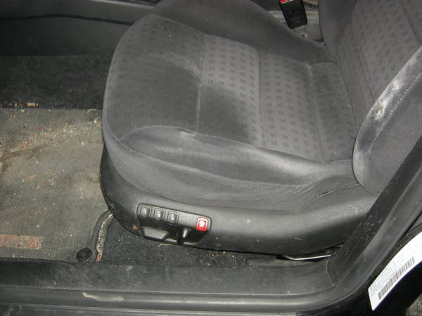
I just finished installing heated memory seats into my 99.5 Golf using the Kufatec 33355 harness. Initially the memory feature didn't work because I didn't wire up the CAN bus wires (I didn't think the 99.5's had CAN bus, but they do - it's just not used for diagnostics). After wiring up the seats to the CAN bus, the memory feature seems to work fine. My new seats are from a 2000 Jetta so they're compatible with the CAN bus in a 99.5 car. It looks like there are 2 different memory seat control modules for MKIV's: 3B1959760A (up to 2001 VIN serial number 900000) and 3B1959760E (starting at 2001 VIN serial number 900001). Make sure your seat controller module is compatible with your particular car.Everything got wired up, but we are having issues with his memory seats. We were testing everything once everything got put back together, and his dome lights kept coming on, and it kept unlocking the car. We disconnected his memory connection under the seat, and it stopped. This definately seems to be the source of the problem. Now, we are trying to figure out what is going on, and what could have gone wrong.
Wiring seems to match the diagrams at the beginning of this post. We had a premade harness from Kufatec, and followed the instructions they provided. The colors of the wires for the memory housing didn't seem to match up with what was in the actually in place, nor did it match up with what Kufatec said they would be, but we matched up the wires on each of the pins to the harness, and studied the Bentley before we hooked anything up. Our only questions were on the three memory wires, pin's 1, 9 & 10 on the memory housing under the drivers seat. 1 ended up going the K wire, pin 7 on the ODB port, and 9 and 10 wen to the Can bus connections on T23 (CCM), pins 6 & 9. Off the top of my head, I don't remembery which was which, but I do believe the colors matched what was posted earlier.
Some notes on the Kufatec harness for anyone that cares:
It took 3 months from the time I ordered (and paid for) the harness for it to actually arrive, and when it finally did it wasn't the right one! They expedited the replacement harness and I got it a week later. Lesson #1: If you're not going to make your own harness, order one well before winter. There was also a wiring error: The wire in the harness that was supposed to go to pin 5 of the red connector on the driver's side went to pin 1 of the same connector instead. Lesson #2: Double-check that the harness was wired correctly before hooking everything up.
The harness didn't come with any instructions and most of the wires were gray. It turns out that most of the wires have tiny printing on them in German that tells you where to connect them. I figured out the remaining ones with a continuity tester and the wiring diagram from Bentley. Here's how I wired everything:
- "Zündungsplus sicherung S5" - Connect this to the black/blue wire at the rear (towards the back of the car) of fuse S5 (7.5 A) in the main fuse box using a wire tap.
- "Beleuchtung Pin 17 Lichtschalter" - Connect this to the grey/blue wire going to pin 17 of the headlight switch connector using a wire tap.
- "Sicherung 44 Dauerplus" - Plug this wire (it should already have a connector preinstalled on the end) into the rear of the empty space for fuse S44. (Don't forget to remove the fuse box's pink locking clip first. Leave the clip out until you install the other fuse S44 wire.)
- "Sicherung S 44" - Plug this wire (it should already have a connector preinstalled on the end) into the front of the empty space for fuse S44. You can now replace the pink locking clip and install a 15A fuse.
- "Schraubklemme KL 30" - Connect this wire (it should already have a ring connector preinstalled on the end) to screw terminal 30 on the relay plate.
- "Masse" - Connect this wire (it should already have a ring connector preinstalled on the end) to a ground point. I used the factory grounding location on the steering column.
- Unlabeled Gray Wire coming from pin 1 of the brown connector - Connect this to the K Line. I soldered it to the grey/white wire going to pin 3 of the 8-pin connector for the radio (it's the bottom one of the 3 connectors). You could also solder it to the grey/white wire going to pin 7 of the 16-pin diagnostics port.
- Unlabeled Gray/White wire coming from pin 9 of the brown connector (CAN Bus High) - I soldered this to the orange/green wire going to pin 6 of the black 10-pin connector at the bottom of the A-pillar behind the hood release handle. You could also solder this to the orange/green wire going to pin 9 of the 23-pin connector on the comfort control module.
- Unlabeled Gray/Yellow wire coming from pin 10 of the brown connector (CAN Bus Low) - I soldered this to the orange/brown wire going to pin 7 of the black 10-pin connector at the bottom of the A-pillar behind the hood release handle. You could also solder this to the orange/brown wire going to pin 6 of the 23-pin connector on the comfort control module.
- Unlabeled Black wire coming from pin 5 of the red connector on the driver’s side - Connect this to the black/brown wire at the rear (towards the back of the car) of fuse S1 (10 A) in the fuse box using a wire tap.
Even though it's listed as being for memory seats, this harness doesn't include the wires needed for the memory mirrors, just the 3 K-line and CAN bus wires needed to talk to the CCM and diagnostics port. Not a big deal to me since I don't have the memory mirrors and I bet it's quite a bit of work to install them and wire them up.
Greg
Last edited:
 for the harness itself.