tongsli
Top Post Dawg
Hello all,
The final diagram:

The final diagram:


")


<font size="2" face="Verdana, Helvetica, sans-serif">I haven't looked to see if Xr -#2 Physically goes into the fuse panel at #36, but there does seem to be a wire in the switch harness.Actually, power for the factory front fogs is via the ignition switch through fuse 36 through the headlight switch (Xr - #2). Then out through NL (#8) to the relay 87, out 30, to the fog lights.
<font size="2" face="Verdana, Helvetica, sans-serif">If this is true, then the "city lights" or amber front turn signal lights are always "hot" no matter what position the Euroswitch is in, right? This makes sense because the turn signal stalk is AFTER the Euroswitch.The control side of the relay is wired to the city lights and high beam circuits according to the Bentley.
<font size="2" face="Verdana, Helvetica, sans-serif">If this is true, then there MUST be an "open" pin location that can serve to keep the relay closed, breaking the path for either power(86) or ground(85) This pin location is probably connected to the "city lights" circuit. Any ideas?When the high beams get turned on, it is no longer a ground path for the control of the relay and thus the relay opens.
<font size="2" face="Verdana, Helvetica, sans-serif">Well, I guess I need to borry someone's OEM non MFA cluster to fool around with the harness and see just what lights up?As for the indicator, it depends on the cluster used. Early A4's had the LED in them; others have not. Replacement MFA clusters have them. This indicator is meant for the rear fogs, but it doesn't really matter. It is pin 14 on the left side connector.

<font size="2" face="Verdana, Helvetica, sans-serif">Lito,Originally posted by tongsli:
I haven't looked to see if Xr -#2 Physically goes into the fuse panel at #36, but there does seem to be a wire in the switch harness.
If Xr does go to the fuse panel, then there is no need for an additional fuse after the relay and as you say, 30 from the relay can feed the fogs.
<font size="2" face="Verdana, Helvetica, sans-serif">Wait... The city lights are not the same as the turn signal lights... These are different lightIf this is true, then the "city lights" or amber front turn signal lights are always "hot" no matter what position the Euroswitch is in, right? This makes sense because the turn signal stalk is AFTER the Euroswitch.[/QB]
<font size="2" face="Verdana, Helvetica, sans-serif">Yes, if the switch physically allows you to turn them on.Originally posted by tongsli:
will the fogs work with the City Lights


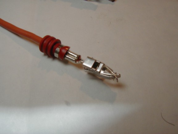
<font size="2" face="Verdana, Helvetica, sans-serif">I would be thankful if somebody could tell me how to pull these wires out of this connector.Originally posted by tongsli:
What I do know so far:
The wire for the fog lights goes into the hole on the right, #2- top row.
The wire connectors to use look like this:
...
<font size="2" face="Verdana, Helvetica, sans-serif">This is not correct. With the Euroswitch in the "center" position, the DRL's are off and the city lights are on. You can still pull the switch to activate the fogs...Originally posted by BRBarian:
</font><blockquote><font size="1" face="Verdana, Helvetica, sans-serif">quote:</font><hr /><font size="2" face="Verdana, Helvetica, sans-serif">Originally posted by GeWilli:
quick comment - on the #3 (TFL) that is the DRL.
If you do not defeat the DRL you will never get just the Fog and City lights. There are the couple ways to do that - #1 tape up the contact...


<font size="2" face="Verdana, Helvetica, sans-serif">Perhaps he has one of those faux ("B") Euroswitches. The "A" switch cuts the DRL's in center position.Originally posted by tongsli:
Hmmm...
GeWilli maybe your wiring is different.
<font size="2" face="Verdana, Helvetica, sans-serif">This is not correct. With the Euroswitch in the "center" position, the DRL's are off and the city lights are on. You can still pull the switch to activate the fogs...Originally posted by GeWilli:
quick comment - on the #3 (TFL) that is the DRL.
If you do not defeat the DRL you will never get just the Fog and City lights. There are the couple ways to do that - #1 tape up the contact...
<font size="2" face="Verdana, Helvetica, sans-serif">Make sure you get the "A" type...
gettin close to goin euro lights (got the switch and rear fogs wired) (hopin Jim doesn't sell out before I get my pennies saved)