rocketeer928 - My 2003 VW Jetta TDI

rocketeer928

Veteran Member
Joined
Jan 24, 2008
Location
Enfield, Connecticut
TDI
2003 Jetta GLS TDI 5-speed
Hi Fellow TDI Friends,


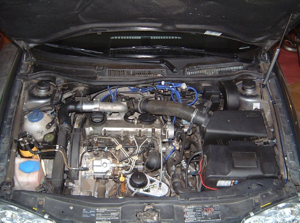
I thought I would finally post my '03 Jetta TDI on this site, which I purchased in Dec 2007. The details are below in my signature. So far, this is the favorite car I've ever owned and the only one I have installed serious modifications. My wife and I lived in Ockenheim, Deutschland (grapevine & wine country) from Dec 2006 through Nov 2007 for my job, and this is where my love for the VW diesel engines was cultivated. My company gave us a 2005 VW Passat Wagon (Kombi) TDI for the year, and for a wagon it was a lot of fun to drive and got 6.4 liters/100 km (35 mpg). Hope you enjoy the pictures.


Last edited:

rocketeer928

Veteran Member
Joined
Jan 24, 2008
Location
Enfield, Connecticut
TDI
2003 Jetta GLS TDI 5-speed
Dyno at Dent Sport Garage in Norwood, MA

Modifications at the time include:

The stock engine is rated at 90 hp / 155 ft-lbs torque. At 118 hp / 215 ft-lbs torque, this translates to an increase of 31% hp / 39% ft-lbs torque.


Last edited:

rocketeer928

Veteran Member
Joined
Jan 24, 2008
Location
Enfield, Connecticut
TDI
2003 Jetta GLS TDI 5-speed
Modifications: May 2009

Over the course of the week of May 22 – 30, 2009, I installed the following modifications on my 2003 VW Jetta TDI:

Garrett VNT 17/22 Hybrid Turbo
MAF to Turbo Intake 2.5-inch OMI
Upgraded 2.5-inch Upper and Lower Intercooler Pipes
3-Bar MAP Sensor
0.658 Fifth Gear
034Motorsport Density Line Dogbone Mount
2.5-inch Downpipe with Catalytic Converter
2.5-inch CAT-Back Exhaust without Muffler
Braided steel turbo oil supply line
CAT Fuel Filter (installed early May; no installation description or pictures)

The following modifications were installed on my Jetta TDI last year:

Unitronic Stage 2 PLUS/EGR Delete chip software
Dieselgeek by-pass filter, short shifter, race pipe, and EGR delete
Bosio PP520 Injector Nozzles
Valeo G60/VR6 Clutch and Flywheel (This by far was the hardest job for me to do.)
TDI FrostHeater

Except for the 0.658 5th gear (see reason below), I installed all of these modifications myself. At this time, I’m still using the OEM 10-mm injection pump and OEM intercooler. Perhaps next year I will consider upgrades to these two components, such as the 11-mm injection pump and a TTT or Eurojet side-mounted intercooler. I spent enough extra money on modifications for this year. On June 20, 2009, I have plans to have the RocketChip RC4 software installed on the Jetta TDI, which will replace the Unitronic Stage 2 PLUS software.

The following posts explain the installation of my latest modifications. I used many different “how-to” documents found on TDI Club and the internet. Unfortunately, some of my pictures are a little blurry because the digital camera I have is rather old and doesn’t do well with close-up shots or it focuses on something else besides what I was going for. Perhaps a fellow TDI enthusiast will find this document helpful.
 
Last edited:

rocketeer928

Veteran Member
Joined
Jan 24, 2008
Location
Enfield, Connecticut
TDI
2003 Jetta GLS TDI 5-speed
Getting the Jetta TDI Ready

Pictures of the engine bay before work began:


Removed engine cover


Loosened lug bolts on the front driver’s side wheel. Removed negative battery connection with a 10‑mm socket. Engaged parking brake and placed into 1st gear.
Securely placed the car on four jack stands.


Removed the bumper to Panzer skid plate skirting with T20 screwdriver. Removed Panzer skid plate with 17-mm socket.


I placed sound proofing material on the underside of the Panzer skid plate to help reduce cabin noise and the retention of heat in the winter.
Removed drive axle boot protective shield that is attached to the engine with a 16-mm socket.


Sprayed PB Blaster on the exhaust bolts and nuts for later removal.
 
Last edited:

rocketeer928

Veteran Member
Joined
Jan 24, 2008
Location
Enfield, Connecticut
TDI
2003 Jetta GLS TDI 5-speed
Bumper Removal

Using a Phillips screwdriver, removed the driver’s side headlight cover.


Removed the grille: First used a flathead screwdriver to unsnap the top of the grill near the hood latch.


Lifted the lower grille next to both headlights.


After the grille is loosened, pulled it out a little to be able to access the bumper bolts. Removed the lower vents by pushing down on the upper portion and pulling at the same time.


Removed the bolts on both sides underneath the vents with a T25 screwdriver.


Removed left front wheel. Removed driver’s side fender housing and mud flap using T20 screwdriver on 12 screws.


Rotated steering wheel all the way to the left and removed the four T20 screws from the passenger’s side fender housing that attach to the bumper.

Removed the five screws from the top of the bumper behind the grille using a T25 screwdriver.


Whoops! Middle finger was not intentional; didn’t notice until I started creating this document.
 
Last edited:

rocketeer928

Veteran Member
Joined
Jan 24, 2008
Location
Enfield, Connecticut
TDI
2003 Jetta GLS TDI 5-speed
Bumper Removal Continued

Removed side marker lights, which will get replaced with clear side markers and amber lights, and unattached bulbs from housing. Disconnected TDI FrostHeater cord from the front of the bumper.


Here is the bumper removed from my Jetta TDI. It seriously needs a re-paint. In fact the whole car could use a re-paint. I’m convinced that the lady who owned this car before me tailgated a sand truck every day to work.

 
Last edited:

rocketeer928

Veteran Member
Joined
Jan 24, 2008
Location
Enfield, Connecticut
TDI
2003 Jetta GLS TDI 5-speed
Headlight Removal and Connector Replacement

Removed both headlights with T20 screwdriver on four bolts each. I have washers underneath the bottom bolts to slightly raise the headlights projection at night.


Disconnected the headlight harnesses. When I first installed these headlights last year, I managed to badly mangle the passenger side headlight harness connector. This is when I was first learning how to disconnect such wiring. So, this was a good opportunity to replace the damaged harness connector.


Removed the purple clip from inside both the damaged and new harness connector.


Using an extraction tool I bought from a fellow TDI Club member, removed one wire at a time and placed into the same position within the new harness connector. Wire numbers 2, 4, 6, 8, & 10 from the top and wire numbers 7 & 9 from the bottom. I have extra wiring for the fog lamp relays.


Re-inserted the purple clip with the grooved channel side out until it clicked in place. Temporarily connected negative battery terminal and tested the headlight and turn signal, which worked!
 
Last edited:

rocketeer928

Veteran Member
Joined
Jan 24, 2008
Location
Enfield, Connecticut
TDI
2003 Jetta GLS TDI 5-speed
034Motorsport Density Line Dogbone Mount Installation

Here’s a picture of the new pendulum mount (dogbone) with new stretcher bolts. The new mount is supposed to dramatically improve engine location with minimal increase in vibration transmission, help reduce engine twisting in modified cars, and improve clutch operation and traction. The mount contains high density 50 durometer rubber, about 25% stiffer than stock the mount. We’ll see.


Supported the transmission with the hydraulic jack to make it easier to remove old and install new dogbone.


Removed four bolts holding the dogbone to the transmission and sub-frame; two with a 13-mm socket and two with a 16-mm socket. Installed the new dogbone. Tightened the two new stretch bolts that go into the sub-frame to 20 Nm (15 ft‑lb) plus an additional ¼ turn, and tightened the two new stretch bolts that go into the transmission to 40 Nm (30 ft‑lb) plus an additional ¼ turn.


I will keep my OEM dogbone for a while in case I don’t like the vibration caused by the new dogbone.
 
Last edited:

rocketeer928

Veteran Member
Joined
Jan 24, 2008
Location
Enfield, Connecticut
TDI
2003 Jetta GLS TDI 5-speed
Turbo Air Intake Pipe and Race Pipe Removal

Removed the connector for the MAF sensor on the air cleaner box. Careful with that clip!


Removed accordion air intake pipe using a hose clamp removal tool. I removed the two hose clamps because I plan to replace them with stainless steel T-bolt hose clamps.


Using the hose clamp tool, removed the rubber elbow between the upper intercooler pipe and the Dieselgeek race pipe. Again, I removed the two hose clamps because I plan to replace them with stainless steel T-bolt hose clamps.


Unplugged the CCV housing connector and carefully removed the CCV.


Removed the two bolts that attach the turbo intake pipe onto the intake manifold with a 10-mm socket.


Using the hose clamp tool underneath, removed the lower intake pipe connection closest to the OEM Garrett VNT-15 turbo.


Removed the turbo actuator vacuum line from the turbo intake pipe; all the way up. See the above picture for one of the connections underneath the engine.

Removed the turbo intake pipe, which will be replaced with the MAF to Turbo Intake 2.5-inch OMI. Carefully twisted out the CCV connector unit. I will keep the OEM turbo intake pipe, just in case...

 
Last edited:

rocketeer928

Veteran Member
Joined
Jan 24, 2008
Location
Enfield, Connecticut
TDI
2003 Jetta GLS TDI 5-speed
Race Pipe Removal

Disconnected the Stewart Warner TDI boost gauge tubing from the Dieselgeek race pipe.


Removed the three bolts and washers attaching the Dieselgeek race pipe to the intake manifold with a 5-mm Allen socket.

 
Last edited:

rocketeer928

Veteran Member
Joined
Jan 24, 2008
Location
Enfield, Connecticut
TDI
2003 Jetta GLS TDI 5-speed
Intake Manifold Removal

Removed the 2-bolt vacuum lines bracket from the intake manifold with a with a 5-mm Allen socket.


Loosened the six intake manifold bolts with a 6-mm Allen wrench and a ¼-inch metal tube about 12-inches long. I discovered this technique when I cleaned my intake manifold, removed the EGR and EGR cooler, and installed the Dieselgeek race pipe after I first purchased my Jetta TDI. Lots of soot… I don’t yet have long metric Allen sockets. As each bolt was loosened, I removed them. From the passenger’s side, bolts number 2 & 6 did not come out until the intake manifold was removed.


Removed the intake manifold and its gasket, which will be replaced upon re-installation.


I inspected the intake holes to the cylinder head with a mirror. There was a little soot, but nothing to fret and lose sleep over.
 
Last edited:

rocketeer928

Veteran Member
Joined
Jan 24, 2008
Location
Enfield, Connecticut
TDI
2003 Jetta GLS TDI 5-speed
Turbo Oil Line Removal

Re-sprayed more PB Blaster on the exhaust system and turbo-to-downpipe nuts for future removal. While pulling up with one hand, loosened the oil supply line on top of the turbo with a 17-mm wrench.


Removed the banjo bolt with two copper washers that connects the oil supply line to the front of the engine with a 17‑mm socket, short extension, and ¼-inch ratchet.


Removed the two clamps that secures the oil supply line and the bracket on the exhaust manifold with a 10-mm socket. Pried the clamps off.


THIS IS THE BLURRIEST PICTURE! Cheap, old camera.

Removed the oil supply line from the engine bay, which will be replaced with a braided steel turbo oil supply line.
 
Last edited:

rocketeer928

Veteran Member
Joined
Jan 24, 2008
Location
Enfield, Connecticut
TDI
2003 Jetta GLS TDI 5-speed
Exhaust System Removal

Underneath, removed the three copper bolts holding the downpipe to the turbo exhaust manifold with a 13-mm socket.


Loosened the exhaust clamp between the downpipe catalytic converter and the rear exhaust system. I had to use a 11/16-inch long impact socket because I did not have an equivalent 18-mm socket. Slid the exhaust clamp toward the front.


Removed the downpipe front support with a 13-mm socket.


Slid out the downpipe and removed the front support. Removed two muffler mount hangers with a 13-mm socket; one in front and one in back. Removed the middle support bracket with a 13-mm wrench. I had to Sawzall the rear exhaust system to completely remove it.

Removed exhaust system.


Here is the new stainless steel 2½-inch downpipe and exhaust system with catalytic converter, new gasket, and new 13-mm copper nuts. There is to be no muffler, since it’s not really needed on the TDI.

 
Last edited:

rocketeer928

Veteran Member
Joined
Jan 24, 2008
Location
Enfield, Connecticut
TDI
2003 Jetta GLS TDI 5-speed
Turbo and Exhaust Manifold Removal

Underneath, removed the bolts on the lower turbo oil return with a 5-mm Allen socket. A new gasket will be needed when this connection is reinstalled.


Underneath, removed the turbo oil line return from the engine with a 22-mm wrench.


Removed the driver side and passenger side engine side shields using a screwdriver to spin the speed nuts.


Removed the lower pancake intake pipe by first unclamping the hoses from the turbo and intercooler with the hose clamp removal tool and then with a 10-mm socket.


Underneath, removed the bolt holding the turbo to the engine bracket with a 13-mm socket.


Removed the two nuts holding the exhaust shield to the exhaust manifold with a 12-mm socket.


Removed the eight nuts and expansion washers that hold the exhaust manifold to the cylinder head with a 12-mm socket. Some of the nuts are hidden and had to be felt in order to get the socket on for removal. Upon removing the two lower passenger side nuts, a bracket holding the bottom of the exhaust shield came off.


Unattached the vacuum line from the turbo actuator.


Lifted the OEM Garrett VNT-15 turbo and its exhaust manifold out from the top of the engine. Removed the gaskets from the cylinder head, which will be replaced.
 
Last edited:

rocketeer928

Veteran Member
Joined
Jan 24, 2008
Location
Enfield, Connecticut
TDI
2003 Jetta GLS TDI 5-speed
Turbo and Exhaust Manifold Removal Continued

I sold this OEM Garrett VNT-15 turbo. It was in good working order and had only 80,000 miles on it.


Since the new turbo came with a new bracket, from underneath removed the turbo-to-engine bracket with a 16-mm socket.


Installed the new bracket loosely onto the engine.


Here is the new Garrett VNT 17/22 Hybrid Turbo.


Notice that one of the bolt studs where the Emissions Gas Recirculation (EGR) delete plate with the Exhaust Gas Temperature (EGT) probe is inserted was slightly bent. I had to pound this bolt stud as straight as possible with a piece of wood and a heavy hammer. I did not drop or cause this bolt stud to be bent. It was shipped like this.
 
Last edited:

rocketeer928

Veteran Member
Joined
Jan 24, 2008
Location
Enfield, Connecticut
TDI
2003 Jetta GLS TDI 5-speed
Windshield Washer Reservoir Removal

For future access to the upper intercooler and the upper intercooler pipe, I removed the windshield washer reservoir with a 10-mm socket (lower plastic bolt) and 10-mm wrench (upper plastic bolt).

 
Last edited:

rocketeer928

Veteran Member
Joined
Jan 24, 2008
Location
Enfield, Connecticut
TDI
2003 Jetta GLS TDI 5-speed
Garrett VNT 17/22 Hybrid Turbo Installation

Installed an EGR delete block plate with a new, metal gasket using new 13-mm copper nuts to 25 Nm (18 ft-lb). The plate has a threaded hole for the EGT probe. Wrapped Teflon tape around the lower brass fitting for the EGT probe and installed on the EGR delete block plate until tightly snug with an 11-mm socket.


Placed four new gaskets on the bolt studs of the cylinder head exhaust ports, ensuring that they are in the correct orientation and that the coated, beaded sides face the 17/22 turbo exhaust manifold. I first placed the 17/22 turbo on a piece of cardboard with the exhaust ports facing upward and then lined up each gasket to make sure they lined up. Then one at a time, placed them on the cylinder head exhaust ports.

Worked 17/22 turbo onto the cylinder head bolts from the top of the engine.


Installed the eight new copper 13-mm nuts with new expansion washers to 25 Nm (18 ft-lb), including the exhaust manifold heat shield bracket on the two lower passenger side bolts.
I tightened the bolts in the following order: 1-8-7-2-5-4-3-6

Reinstalled the exhaust manifold heat shield with two new copper 13-mm nuts to 25 Nm (18 ft-lb). I used two washers from the removed turbo, since the Bentley manual shows the washers. I had to slightly bend downward the bottom of the heat shield to fit in its bracket.


Using a new paper gasket, reinstalled the turbo oil return line with a 22-mm wrench until good and tight and a 5-mm Allen socket to 15 Nm (11 ft-lb). I used a little fresh oil to keep the paper gasket in place during the installation. I also added a little fresh oil into the 17/22 turbo oil inlet for the initial start-up.
 
Last edited:

rocketeer928

Veteran Member
Joined
Jan 24, 2008
Location
Enfield, Connecticut
TDI
2003 Jetta GLS TDI 5-speed
Lower Intercooler Pipe Installation

At this point I discovered that the hose from the 17/22 turbo to the lower intercooler pipe must be installed prior to tightening down the exhaust manifold. On the 17/22 turbo, the air outlet rests up against the engine block. There was absolutely no clearance for the lower hose and its hose clamp. Therefore, I had to loosen all of the exhaust manifold nuts. Ugh!!


Removed the lower intercooler bolt with a 10-mm socket because upon fitting I discovered that the lower intercooler pipe was slightly too long, and I did not want to cut it shorter. Installed the new lower intercooler pipe from the 17/22 turbo to the intercooler. I had to use a regular screw clamp for the hose that attaches to the 17/22 turbo because I did not have a small enough stainless steel T-bolt hose clamp. My hope is that the screw clamp will hold since it was going to be tight up against engine block due to the non-existent clearance described above. I have smaller stainless steel T-bolt hose clamp on order, just in case… The intercooler is moved out slightly because of the length of the lower intercooler pipe. Stainless steel T-bolt hose clamps were used for all other connections. The rubber grommet for the 10-mm lower intercooler bolt was removed so that the bolt could be reinstalled, which was difficult. Tightened until snug.


Once the lower intercooler pipe was installed, the nuts on the exhaust manifold were re-tightened to 25 Nm (18 ftlb).
 
Last edited:

rocketeer928

Veteran Member
Joined
Jan 24, 2008
Location
Enfield, Connecticut
TDI
2003 Jetta GLS TDI 5-speed
Stainless Steel 2½-inch Downpipe and CAT-back Exhaust System Installation

Lubricated all the rubber exhaust system mount holders with silicone lubricant. Loosely installed the downpipe and dual pipe CAT‑back exhaust system by loosely attaching onto the brackets. It was immediately obvious that the pipes were too long, and that there was no way the exhaust system would be easily fitted together.

It took me about 5 hours to install the entire exhaust system, with A LOT of frustration. The exhaust system was definitely not plug-and play. I had to remove about ¾-inch from both the downpipe and the back-end pipe to get a proper fitment. The middle pipe could not be cut on either end because I would not have been able to use the exhaust clamps. After cutting, I loosely fitted all the pipes, two clamps, and brackets. I tightened the nuts and bolts in the following order:

  1. Downpipe to exhaust manifold with new copper nuts with a 13-mm socket to 25 Nm (18 ft‑lb). One of the nuts I had to hand tighten to firmness because my torque ratchet would not fit with any combination of 13‑mm sockets and extensions
  2. Front support mount to the downpipe with a 13-mm socket to 25 Nm (18 ft‑lb)
  3. Middle support mount with a 13-mm wrench hand tightened because my torque ratchet would not fit
  4. Exhaust clamp between the downpipe and the middle pipe with an 11/16-inch long impact socket to 40 Nm (30 ft‑lb)
  5. Front and rear muffler mounts (no muffler) with 13-mm socket to 25 Nm (18 ft‑lb)
  6. Exhaust clamp between the middle pipe and the end pipe with an 11/16-inch long impact socket to 40 Nm (30 ft‑lb)

I had to use a box-cutting knife on the lower bumper skirting, since the down-turned exhaust tip was still too long. Also, the middle and end pipe are slightly crooked, which I believe is because the mounting bars were welding on in the wrong places. I am considering grinding down the tip to make it appear straight.


The twist on the middle bracket can be seen here.


Definitely crooked here!!
 
Last edited:

rocketeer928

Veteran Member
Joined
Jan 24, 2008
Location
Enfield, Connecticut
TDI
2003 Jetta GLS TDI 5-speed
Emission Gas Temperature (EGT) Probe Installation

Fed the EGT probe through the firewall grommet above the acceleration pedal. Placed the brass fitting and ferrule onto the EGT probe and bent the probe very slightly. Using Teflon tape on the threads, pushed the probe into the EGR delete block plate connector as far as it would go, which bends the probe. Actually, I had to remove the EGR delete block plate to get the probe to bend properly, and re-tighten to 25 Nm (18 ft‑lb). Tightened the brass fitting with a 7/16-inch wrench until snug.

 
Last edited:

rocketeer928

Veteran Member
Joined
Jan 24, 2008
Location
Enfield, Connecticut
TDI
2003 Jetta GLS TDI 5-speed
Braided Steel Turbo Oil Supply Line Installation

Removed the oil line connection union from the top of the 17/22 turbo to replace it with the braided oil line connection union.


The original union has a copper washer, while the union for the braided line has an O-ring and aluminum washer. A little dab of grease was used to keep the aluminum washer onto the connection union as I installed it on top of the 17/22 turbo with a 14-mm socket to 40 Nm (30 ft‑lb).


The original OEM turbo oil supply line banjo bolt was replaced with the braided oil line connection union, including a washer and O-ring. The transmission was in the way to use my torque wrench, so I tightened with a 17-mm socket with a 3/8‑inch ratchet until as tight as possible.


Reinstalled the rear clamp mounting bracket for the braided turbo oil supply line with 13-mm socket to 25 Nm (18 ft-lb). Placed the upper clamp on the oil line. Fed the braided oil line to the top of the 17/22 turbo and hand threaded, which was difficult. Fed the braided oil line to the lower oil connection union and hand threaded. Removed the vacuum reservoir with an 8-mm wrench. Tightened the upper and lower unions with a 15-mm wrench. Reinstalled the upper and lower securing clamps on the braided oil line with a 10-mm socket to 10 Nm (7 ft-lb), and reinstalled the vacuum reservoir.


Last edited:

rocketeer928

Veteran Member
Joined
Jan 24, 2008
Location
Enfield, Connecticut
TDI
2003 Jetta GLS TDI 5-speed
Intake Manifold & Dieselgeek Race Pipe Installation

A new gasket was used on the intake manifold with the raised, beaded side facing the manifold. Placed Nr. 1, 2, and 6 hex bolts into the intake manifold and its gasket prior to installing on the cylinder head. Hex bolts Nr. 1 and 2 need to be preinstalled because of the exhaust manifold heat shield. Threaded all 6 bolts by hand. I don’t have long hex sockets, so hand tightened with a 6-mm Allen wrench and hollow metal tubing to torque to a good, firm tightness in the following order: Bolt Nr. 5, 2, 1, 6, 3, and 4. Re-check tightening. I had to remove and then re-install the upper braided turbo oil supply line clamp.


Reinstalled the 2-bolt vacuum line bracket onto the intake manifold with a 5-mm Allen wrench.

Removed the brass boost gauge tubing connector from the DG race pipe with an 11-mm long socket.


Installed McNally boost gauge external pressure sensor connector onto the DG race pipe with an 11/16-inch wrench. The threads were wrapped in Teflon tape.


Applied a thin coat of oil on a new DG race pipe O-ring gasket, and reinstalled with a 5-mm Allen socket to 10 Nm (7 ft-lb).

 
Last edited:

rocketeer928

Veteran Member
Joined
Jan 24, 2008
Location
Enfield, Connecticut
TDI
2003 Jetta GLS TDI 5-speed
OEM Upper Intercooler Pipe Removal

Unhooked the wire conduit from underneath the OEM upper intercooler pipe.


In the above picture you can see the yellow CAT 2‑µm fuel filter that installed a few weeks before.

Disengaged the spring clamp holding the upper intercooler pipe with a spring clamp tool.


Noted that the headlight wires are above the upper intercooler pipe. Removed the upper intercooler pipe through the hole for the headlight.

 
Last edited:

rocketeer928

Veteran Member
Joined
Jan 24, 2008
Location
Enfield, Connecticut
TDI
2003 Jetta GLS TDI 5-speed
2½-Bar MAP Removal and 3-Bar MAP Installation

Unplugged the connector to the 2½-Bar MAP. Carefully unscrewed the two Philips screws holding the 2½-Bar MAP in placed. I had been told that the head of these screws tend to snap, but mine did not.


Picture of the 3-Bar MAP (left) and 2½-Bar MAP (right).


Installed the 3-Bar MAP. I didn’t seem to need the extra supplied grommet that was supplied, though I kept it just in case… Carefully tightened the screws.
 
Last edited:

rocketeer928

Veteran Member
Joined
Jan 24, 2008
Location
Enfield, Connecticut
TDI
2003 Jetta GLS TDI 5-speed
Stewart Warner Boost Gauge Removal and McNally Boost/EGT Gauge Installation

Plugged the connector for the external pressure sensor wires into the sensor installed on the DG race pipe, and fed the wires through the firewall.


Carefully removed the 0-30 psi Stewart Warner (SW) boost gauge. Peeled back the rubber/fabric door weather stripping at the top of the A-pillar. Pulled back the top of the A-pillar to view the 2-piece clip. To release the clip, slid the bottom portion out from the top portion with a dental hook. Pulled the A-pillar trim away from the frame. With pliers, remove the top portion of the clip from the frame, which mangled it so that I had to use a new clip upon reinstallation. Here's a link I used to remove clip: http://forums.vwvortex.com/zerothread?id=1512666

Removed all the wiring associated with the SW gauge. Using the SW pressure tubing and tape, fed the EGT and external pressure sensor (except black ground) wires up through to the A-pillar trim and through the hole into the gauge pod. Fed the Boost/EGT power and ground wires through the gauge pod hole down to the side fuse area. Inserted all the wires into the gauge connector according to the McNally instructions.

Spliced the Boost/EGT gauge and external pressure sensor black ground wires into the Nr. 31, brown light switch wire, which leads to ground. Using an O-crimp connector, wired the red, 12-volt wire from the Boost/EGT gauge to the 75X switched 12-volt connection underneath the dash. Installed an in-line 10-amp fuse for the 12-volt wire.


To reinstall the A-pillar trim, inserted the top portion of a new clip into the square hole on the trim. Slid the bottom portion of the clip back into place, securing the two-part clip into the trim. Popped the trim back into the frame and reinstalled the rubber/fabric weather stripping.

A-Pillar Clip Part Numbers: 1J0-880-385-A and 1J0-880-287


I sold the SW boost gauge, Perfect Match Blue LED, and the LED regulator.
 
Last edited:

rocketeer928

Veteran Member
Joined
Jan 24, 2008
Location
Enfield, Connecticut
TDI
2003 Jetta GLS TDI 5-speed
New “Old Man Intake” (OMI) Installation

The OMI had to be fitted to the 17/22 turbo intake and the intake manifold by trial and error.


The blue hose that connects the OMI to the 17/22 turbo had to be fitted at the right depth and angle. About 1½ inches of the blue hose had to be trimmed off the side that connects to the 17/22 turbo. After fitment, a screw clamp was fitted to the hose and 17/22 turbo connection because I did not have a stainless steel T-bolt clamp that would fit.


A stainless steel T-bolt was fitted to the blue hose and OMI connection. The bolts to secure the OMI to the intake manifold were tightened to a firm tightness with a 10-mm socket.


Placed a little grease on the CCV to OMI connector unit and carefully installed. Plugged in the CCV harness connector and reinstalled the CCV. The hose between the CCV and OMI is a little stretched. I’m going to consider installing a strainer in what is called the “KCTDI-CCV Kit” to help reduce the amount of oil that is allowed into the intake, since I have already eliminated the EGR and its cooler.


Reinstalled the accordion hose between the OMI and air cleaner box using two stainless steel T-bolt clamps, and reinstalled the MAF sensor connector.


Reinstalled the drive axle boot protective shield to the engine block with a 16-mm socket at 35 Nm (26 ft-lb).

 
Last edited:

rocketeer928

Veteran Member
Joined
Jan 24, 2008
Location
Enfield, Connecticut
TDI
2003 Jetta GLS TDI 5-speed
Upper Intercooler Pipe Installation

The upper intercooler pipe was not long enough to reach the rubber elbow that connects to the DG race pipe. Fortunately, an approx. 3-inch metal tube the same diameter as the upper intercooler pipe was shipped along with the parts (must be a reason don’t you think?). I stretched the OEM rubber hose that went between the OEM air intake tube and the OEM VNT 15 turbo on the extra metal tube and the upper intercooler pipe. This combination provided just enough length to the rubber elbow with the use of an extra stainless steel T-bolt clamp.


Last edited:

rocketeer928

Veteran Member
Joined
Jan 24, 2008
Location
Enfield, Connecticut
TDI
2003 Jetta GLS TDI 5-speed
Reinstallation of Remaining Components

Secured the 3-Bar MAP wire that had ran along the top of the OEM upper intercooler pipe along the power steering hose with cable ties.

Attached the two connectors to the windshield washer reservoir. Reinstalled windshield washer reservoir using a 10-mm socket and 10-mm wrench until snug. Make sure that the windshield washer pump tubing is not trapped underneath the reservoir (found out the hard way).

Made a fresh cut into the vacuum line for the 17/22 turbo actuator and pressed firmly onto the actuator. Loosely secured the actuator vacuum tubing and external pressure sensor wires together next to the firewall with a cable tie.


Reinstalled the driver’s side plastic fender cover with T20 screws.

Substituted the side marker bulbs with amber bulbs.

Reinstalled headlights. The right headlight was difficult to reinstall because the upper intercooler pipe interferes. Gentle persuasion was applied...

Reinstalled bumper, including new, clear side markers. Amber side marker bulbs: Sylvania Bulb Nr. 2827

Reinstalled grille, left, front wheel, driver’s side headlight cover.

Reconnected the negative battery terminal and reinstalled the battery cover.

Reinstalled the engine side shields. I had to trim a little off of the passenger engine side shield to accommodate the lower intercooler pipe.

Lowered the car off of the jack stands and torque the left, front wheel to 120 Nm (89 ft-lb).

Pushed the car out of the garage and placed on the front jack stands again.

The car started right up. Checked for air, exhaust, and oil leaks, and there didn’t appear to be any such leaks.

I tried to replace my 0.756 fifth gears with the 0.658 fifth gears to lower the rpm on the highway. However, over the course of three days and help from fellow TDIers, I simply could not remove the T60 selector gear bolt. I even tried heating the gear and using a very long breaker bar. I ended up reinstalling the few parts I did remove, putting the transmission cover back on, and refilling with fresh transmission fluid. I had to take my car to my local garage (Farnbacher Loles in Danbury, CT) to install this fifth gear, and the car is at the garage still (June 5, 2009) because I managed to damage a C-clip while heating the gear. Very disappointed that I could not do this job myself. I learned from my mechanic that I should have heated the bolt I wanted to remove, rather than the gear around the bolt.


I ordered more stainless steel T-bolt clamps of sizes that I did not already have, since the car has two screw clamps that I had to install. I don’t intend to replace the screw clamp holding the hose from the 17/22 turbo to the lower intercooler pipe unless a problem occurs. To do so would mean loosening the exhaust manifold and 17/22 turbo, which I would rather not do.

However, I did decide to replace the screw clamp that was installed on the blue hose for the 17/22 turbo intake from the OMI. The new T-bolt clamp was a tight fit to install, but it did finally go on. To install, I had to remove the two 10-mm bolts holding the OMI to the intake manifold. Upon reinstallation of the OMI, I managed to strip both of the threads on the aluminum intake manifold with the 10-mm bolts. Ugh! I was able to drill out the top hole with a ¼-inch drill bit, thread the hole, and install a heli-coil insert. However, the other stripped hole is on the side of the intake manifold and cannot be reached with a drill. I tried to fix the problem by hand, but with no success. Maddening… So, I will be forced to remove the intake manifold once again to install the heli-coil insert. I did recently purchase long metric hex sockets, which I am hoping will make removal easy and installation to the correct torque setting.

I plan to install a Eurojet Side-Mount Intercooler and Vented Fender Housing very soon.

So far, I have been driving my Jetta TDI rather carefully. I don’t want to over-boost the new 17/22 turbo. I plan to have the car tuned with the RocketChip RC4 software on June 20th.
 
Last edited:

JettaJake

Veteran Member
Joined
Nov 26, 2002
Location
CT TDI Corral
TDI
'03 GLS 5spd
I cannot see the pictures ('cause I am at work) but will look when at home this evening -- we have nearly identically modded cars, btw :D 
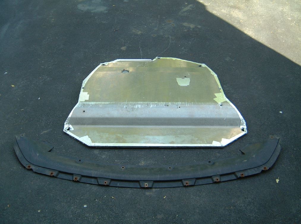
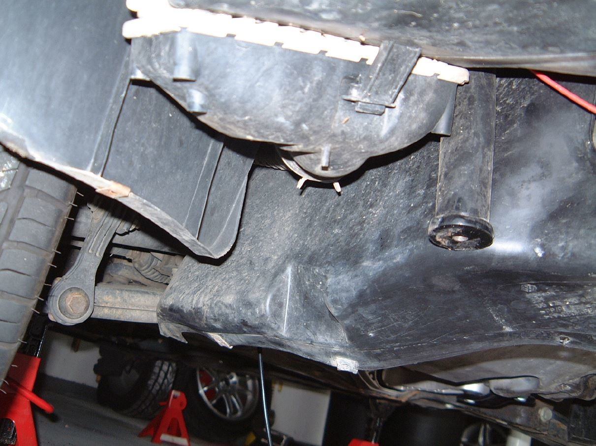
(did I miss mudflaps/splashguards? :) )
 

shizzler

Veteran Member
Joined
Jun 25, 2005
Location
Ann Arbor MI
TDI
05 BEW Wagon
Wow. That's some dedication to modification documentation. Basically one giant DIY thread!

Thanks for sharing, nice job on the mods. Bet you can't wait for the RC tuning!
 
Top