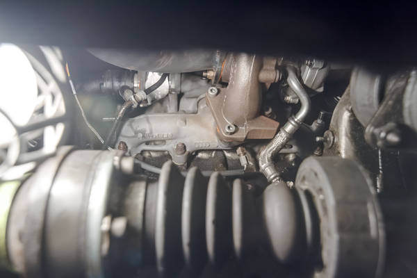
How far does your thermocouple get into the exhaust stream?I have mine right where the streams converge just before getting to the turbo:
You drilled /tapped the manifold in the car?

How far does your thermocouple get into the exhaust stream?I have mine right where the streams converge just before getting to the turbo:
Ok, after Asking this question myself, I searched and found somebody had made a cover, and a back plastic plate for these displays. I uploaded them into 3d builder which is included in windows 10 for free, and then sent them off to a 3d printer, right thru the program, pretty easy, and they seem decent. I can't upload attachments, yet, so they are on my dropbox. I have included pics, and a screenshot of 3d builder, and the files. Thank you to Aknovaman for sharing this, there are so many possiblities for guages now.Has anyone come up with an idea for an enclosure yet? I'm still waiting on my arduino boards to arrive, but have the other components.
This is probably a dumb question, but where exactly would I attach the thermocouple on the car?
How is the brightness holding up? Any aging you can tell?I have run these displays for about a year 24/7 without failure.

#include <Adafruit_GFX.h>
#include <Adafruit_SSD1306.h>
int OLED_RESET = 4;
Adafruit_SSD1306 display(OLED_RESET);
float Vcc_Per_ADC = 0;
void setup() {
Serial.begin(9600); //To comunicate with the PC
display.begin(SSD1306_SWITCHCAPVCC); //To supply the 3.3V power supply
pinMode(0, INPUT); //Set analog pin 0 as an input from the sensor
pinMode(1, INPUT); //Set analog pin 1 as an input from the sensor
display.clearDisplay(); //Clear the display and ram
Vcc_Per_ADC = readVcc()/1024.0; //initialise the calbration of ADC voltage
delay(500);
}
void loop() { // Start loop
static int raw_bst = 0; // Setup raw boost sensor value
static int raw_emp = 0; // Setup raw emp sensor value
static int peak_raw_bst = 0; // Setup peak boost value
static int peak_raw_emp = 0; // Setup peak emp value
static int peak_raw_bst_st = 0; // Setup peak boost value last two minutes
static int peak_raw_emp_st = 0; // Setup peak emp value last two minutes
static int grphboost = 0; // Setup value for boost bar
static int grphemp = 0; // Setup value for boost bar
static int bst_bar = 0; // Setup boost value
static int emp_bar = 0; // Setup boost value
static int bst_barpeak = 0;
static int emp_barpeak = 0;
static int bst_barpeak_st = 0;
static int emp_barpeak_st = 0;
static int x = 0; //counter
static int samples = 20;
static int sample_interval = 8;
static unsigned long lasttime = 0;  //time value to reset peak every two minutes
Vcc_Per_ADC = (9*Vcc_Per_ADC + readVcc()/1024.0)/10.0 ; //calibrate the ADC voltage with a running average to smooth noise
raw_bst = analogRead(0); // Read MAP sensor raw value on analog port 0
raw_emp = analogRead(1); //Read MAP sensor raw value on analog port 0
delay(sample_interval);  //wait as per following routine between raedings
for(x = 0; x <= (samples-2); x++) { //loop to average a few readings
raw_bst += analogRead(0);
raw_emp += analogRead(1);
delay(sample_interval);
}
raw_bst =  int ((raw_bst/samples)+0.5); //get avergage and convert to integer
raw_emp = int ((raw_emp/samples)+0.5); //get average and convert to integer
//vw 4 bar sensor p bar = V volts x 0.85261 + 0.1581 bar
//vw 4 bar formula = raw x 0.003911 + 0.1581
bst_bar = int (((raw_bst*Vcc_Per_ADC*0.85261/1000) + 0.1581)*10-10+0.5); // Calculate manifold bar from raw value
//Mcnally 75psi p bar = V volts x 1.293 - 0.647bar //think 500mV=0mBar absolute, 4500mV=75psi
//Mcnally raw x 6.743 - 1.439bar
emp_bar = int (((raw_emp*Vcc_Per_ADC*1.293/1000) -  0.647)*10-10+0.5); // Calculate emp from raw value
grphboost = int ((bst_bar) * 3.2); // Calculate boost value for the bargraph 4 secions 125 pixels wide total
grphemp = int ((emp_bar) * 3.2); // Calculate boost value for the bargraph 5 secions 125 pixels wide total
if ( millis() - lasttime > 120000) {
lasttime = millis();
peak_raw_bst_st = 0;
peak_raw_emp_st = 0;
}
if (raw_bst > peak_raw_bst){ // If current boost is higher than peak, store new value
peak_raw_bst = raw_bst ; // Store new peak value in peak memory
bst_barpeak =  (((peak_raw_bst*Vcc_Per_ADC*0.85261/1000) + 0.1581)*10-10); //
}
if (raw_bst > peak_raw_bst_st){ // If current boost is higher than peak, store new value
peak_raw_bst_st = raw_bst ;
bst_barpeak_st =  (((peak_raw_bst_st*Vcc_Per_ADC*0.85261/1000) + 0.1581)*10-10); //      (((peak_raw_bst_st * 0.003911) + 0.1581)*10-10);
}
if (raw_emp > peak_raw_emp){ // If current boost is higher than peak, store new value
peak_raw_emp = raw_emp ; // Store new peak value in peak memory
emp_barpeak = (((peak_raw_emp*Vcc_Per_ADC*1.293/1000) -  0.647)*10-10);     //
}
if (raw_emp > peak_raw_emp_st){ // If current boost is higher than peak, store new value
peak_raw_emp_st = raw_emp ; // Store new peak value in peak memory
emp_barpeak_st = (((peak_raw_emp_st*Vcc_Per_ADC*1.293/1000) -  0.647)*10-10);     //(((peak_raw_emp_st *0.006743) - 1.439)*10-10);
}
display.display();
display.clearDisplay();
display.setTextColor(WHITE);
send_pres_to_oled(10,7,4,emp_bar); //send emp
send_pres_to_oled(72,7,4,bst_bar); //send boost
send_pres_to_oled(68,45,2,emp_barpeak_st);
send_pres_to_oled(100,45,2,bst_barpeak_st);
send_pres_to_oled(4,45,2,emp_barpeak);
send_pres_to_oled(36,45,2,bst_barpeak);
display.drawRect(1, 40, 131, 24, WHITE); //Border of the bar chart
display.drawLine(32,40,32,63, WHITE); //draw bar boost markers
display.drawLine(64,40,64,63, WHITE); //draw bar boost markers
display.drawLine(96,40,96,63, WHITE); //draw bar boost markers
//display.drawLine(125,40,125,63, WHITE);
display.fillRect(1, 40, grphboost, 9, WHITE); //Draws the bar depending on the sensor value
display.fillRect(1, 55, grphemp, 9, WHITE); //Draws the bar depending on the sensor value
display.drawRect(1, 1, 127, 63, WHITE); //Border of the entire screen
//delay(100);
}
long readVcc() {
long result;
// Read 1.1V reference against AVcc
ADMUX = _BV(REFS0) | _BV(MUX3) | _BV(MUX2) | _BV(MUX1);
delay(2); // Wait for Vref to settle
ADCSRA |= _BV(ADSC); // Convert
while (bit_is_set(ADCSRA,ADSC));
result = ADCL;
result |= ADCH<<8;
result = 1076490L / result; // Back-calculate AVcc in mV
//Serial.println(result);  //use this to adjust line above to calibrate readVcc should be the same as measure on 5v pin or Vref pin, mine read 4.71 volts on usb supply
return result;
}
void send_pres_to_oled(int first_pos,int height_pos, int text_size,int press_val){
//first_pos = 10, second_pos = 35, height_pos = 7 , text_size = 4
display.setTextSize(text_size);
display.fillRect(first_pos + 6* text_size, height_pos + 6 * text_size , text_size, text_size, WHITE); //decimal point
if (press_val < 9.5)  {    //anything from 9.5 upwards would be rounded to 10 so using two chars
if (press_val < 0) {   //deal with negative as normal negative requires entire char width
press_val = press_val*-1;
display.fillRect(first_pos-1, height_pos-text_size, 2*text_size, text_size/2, WHITE);
}
display.setCursor(first_pos, height_pos);
display.println(0);
display.setCursor(first_pos + 7*text_size, height_pos);
display.println(press_val);
}
else   {
display.setCursor(first_pos, height_pos);
display.println(press_val);
}
}Would you have a written list of wiring connections? I have to watch the video again. So far, I figured that SCL on the OLED goes to A5 on the nano, and SCM goes to A4. Kind of a PITA that there's only one connector for VCC, but 2 for ground.If necessary I can write step by step directions on how to set up the software to load the sketch. Just need a few days.
I just used cat-5 cable wires cause they are solid/semi-rigid and free.
Windex, Here is a link to the wiring connections.
https://youtu.be/x6wSGZ9bYPk
")
If I recall correctly, someone offered to make a 3D printed case. .????????
Looks very good but you should post your code too so others can benefit.Here is my new version . I used a little part of code from Chapelhill to save peak value .
I love Arduino
https://www.youtube.com/watch?v=bdnQrl0PDNA
//Arduino nano , 1.3" I2C OLED

#include <Wire.h>
#include <Adafruit_GFX.h>
#include <Adafruit_SH1106.h>
#define sensorPin 0

int OLED_RESET = 4;
Adafruit_SH1106 display(OLED_RESET);

// bar graph

float rawval = 0; // Setup raw sensor value
float barboost = 0; // Setup value for boost bar

// peak

int boostPeakReset = 4000; // time in milis to reset peak value
float boostPeak = 0.00;
float boostMax = 0.00;
unsigned long boostPeakTimer = 0;

// log

byte count;
byte sensorArray[128];
byte drawHeight;
boolean filled = 0; //decide either filled, or dot-display. 0==dot display.


void setup()
{
  display.begin(SH1106_SWITCHCAPVCC); // 3.3V power supply
  display.clearDisplay(); // Clear the display and ram
  for (count = 0; count <= 128; count++) //zero all elements
  {
    sensorArray[count] = 0;
  }
}


void loop() // Start loop
{
  int boostmbar = map(analogRead(sensorPin), 21, 961, 100, 2600);
  rawval = analogRead(0); // Read MAP sensor raw value on analog port 0
  barboost = (((rawval * 0.19) - 69.45) + 10); // Calculate boost value for the bargraph


  if (boostPeak < boostmbar && boostmbar > 0.50) {
    boostPeak = boostmbar;
    boostPeakTimer = millis();
    if (boostMax < boostPeak) {
      boostMax = boostPeak;
    }
  }
  else if (boostPeak > boostmbar && (millis() - boostPeakTimer) > boostPeakReset) {
    boostPeak = 0.00;
  }


  // log

  drawHeight = map(analogRead(A0), 0, 1023, 0, 25 );

  sensorArray[0] = drawHeight;

  for (count = 55; count <= 128; count++ )
  {
    if (filled == false)
    {
      display.drawPixel(count, 71 - sensorArray[count - 55], WHITE);
    }
    else
      display.drawLine(count, 1, count, 71 - sensorArray[count - 55], WHITE);
  }

  for (count = 80; count >= 2; count--) // count down from 160 to 2
  {
    sensorArray[count - 1] = sensorArray[count - 2];
  }

  display.drawLine(55, 43, 55, 64, WHITE);
  display.setTextColor(WHITE);
  display.setTextSize(4);
  display.setCursor(0, 0);
  display.println((boostmbar * 0.001) - 0.97);    // 0.97 = 970mbar atmospheric pressure correction

  display.drawRect(0, 31, 128, 12, WHITE); // Border of the bar chart
  display.fillRect(0, 31, barboost, 12, WHITE); // Draws the bar depending on the sensor value

  display.setTextColor(WHITE);
  display.setTextSize(1);
  display.setCursor(97, 20);
  display.println("BOOST");

  display.setTextSize(2);
  display.setCursor(3, 48);
  display.println((boostPeak * 0.001) - 0.97); // 0.97 = 970mbar atmospheric pressure correction


  if (2700 < boostmbar ) {
    display.setTextSize(1);
    display.setCursor(105, 5);
    display.println("MAX");
  }
  else if (2700 > boostmbar ) {
    display.setTextSize(1);
    display.setCursor(105, 5);
    display.println("");
  }

  delay(1);
  display.display();
  display.clearDisplay();
}Going to try these and modify code as needed.
https://youtu.be/NBp3t_gHTkE
https://youtu.be/QDIZqIueSIU
https://youtu.be/sneQN4bpirg