Okay, as the edit in the last post said, I got the tranny up and in....everything connected, bolted, etc.
I had issues with the wiring for the Engine Temp Sensor relay power circuit and did not have time to install the front sway bar. More about that problem below.
Anyway, here are a few pics of the Bell Housing, Pressure plate, etc.
Below, is a pic showing the approximate distance from the pilot shaft over to the area where the pressure plate was making contact with the bell housing. (shiny spots)
Below, in this pic, you can see that five inches is to the outer edge of the area of the pressure plate where it was making contact with the flywheel... Also, notice there toward the bottom of the pic is one of two V-shaped tabs. I knocked those down a wee bit. (notice, I had to use the ALH dust shield between the engine and bell housing, worked fine)
Below, in this pic you can see the "spots" where I had to remove material from the bell housing to allow clearance for the pressure plate. The far left center is where the V-shaped tabs where making contact.
Below, is a close-up, left side of the bell housing looking toward the front of the Vanagon.
Below, is a close-up, right side of the bell housing looking toward the front of the Vanagon.
Below, is a close-up of the pressure plate showing the two V-shaped tabs after I knocked them down just a wee bit. (foregournd -background)
........................................................................................................................................
The following three photos pertain to my efforts to install a Relay in the Coolant Temp Sensor (CTS) circuit.
For Ignition power to the Relay, I had to run another circuit. I didn't want to just "hang" a wire from the dash under the Van to the rear. So, I attempted to "squeeze" one more wire into a small polyethelyne tube that already had 7 wires in it. I sort of screwed up and almost didn't accomplish the goal (long story).
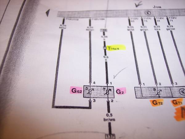
Below, is a pic of the wiring schematic of the CTS circuit. Notice that the ETS is actually two sensors. G62 provides data for the ECU and G2 provides data to the Cluster for the Temp Gauge.
From the CTS connector, I will be installing a Relay in the circuit coming off #4 that goes to T121/104 of the ECU (ECU is represented by the dark bar in background). The circuit will be closed (normal) when the Ignition is ON. The power for the Relay will come from an X Circuit at the dash. X Circuit current is cut OFF during the Start mode of the Ignition.....thus, the Relay will open and the CTS can no longer send the ECU a reading. Then, the ECU will default to a reading of -40F/C. Next, it will respond by. increasing the fuel amount during START. (same as unplugging the CTS)
Below, in this pic, you can see that I have pulled the connector to the CTS and peeled the four wires out of the protective cover.
Below, in this pic, you can see the wire that will be cut for re-routing thru the Relay. I have not finished mounting the Relay nor completed the circuits.