ALH Injection Pump re-seal
Okay, here are the pics of the Injection Pump re-seal task. Please note: don't do this at home without watching the YouTube link (all 7 flicks) in RunonBeer's signature. Also, I am only posting to show what I did and this is not to be considered as "re-inventing the wheel."
So, with that in mind, I will post a number of the pics I took today with diesel fuel on my fingers/camera, etc. Nope, I did not use rubber gloves as the Diesel Geeks guys did.
First, I stress (re-stress what the DG guys said) ...... keep things clean. If my engine wasn't so nice and clean, I would have pressure washed it first.
Anyway, I did use parts cleaner and compressed air to start-off being clean and staying clean!
This will probably take three or more posts (
all comments are at the top of the pics)
This pic is illistrative of what I'm trying to get across about being clean. Also, I used lots of paper towels (not shop towels) and clean old cotton rags.
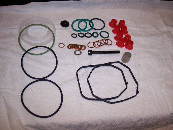
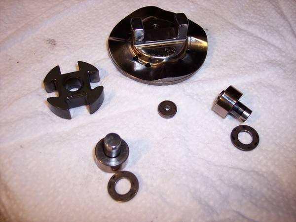
Below is what comes in the re-seal kit. Notice on the left bottom are two Viton O-rings (ordered separately, because they are not in the kit). I'm not sure why there were two in the unopened/sealed bag. They were smaller (less fat) than the Green One that come with the Bosch kit... Yep, I did not use the Viton seal...........explain to me why there were two of them. I didn't want to take any chances on a screw-up. And, I didn't have time to be chasing down this sort of thing.
Totally unnecessary, but I did set the engine on TDC. In fact, to get the IP internally "on high" cam, the IP pin had to be removed. (this is informational only)
Below, is the top of the IP removed and laying back away from the work area. I did cover it with a paper towel.
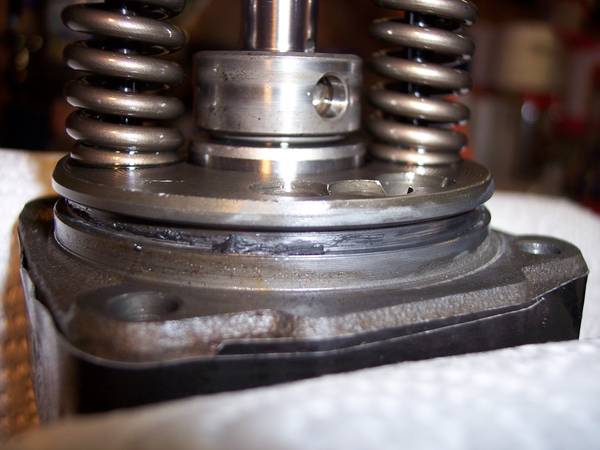
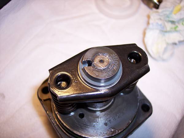
Below, is a view of the QA with the top of the IP off. Notice there is fuel all around the sides ,,,, indicating it is probably not leaking back. The vehicle had been sitting at least 6 hours before I removed the pump top.... plenty of time for a leaking O-ring, fuel line, or filter connection to leak down.
Below is another angle of the QA adjuster with the top off.
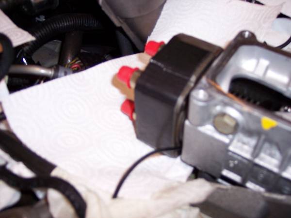
In the pic below, you can see that I have removed number 3 & 4 injector lines and installed the red protector covers. The other two injector lines were removed next.
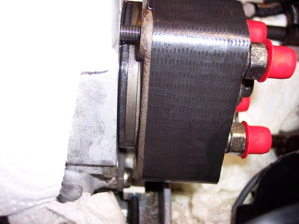
In the pic below, I am trying to show the "mark" I made on the pump body and the Quantity Adjuster ...... it is straight down from the gold colored bolt there.... not in focus, but there.
This pic, better shows the mark on the pump body and QA. In fact, I marked it just below both gold colored bolts on that side. (not talking about the yellow paint, that's factory). Putting the QA back "in alignment" is very important when you are ready to start the engine. If it is off just a little, the starting and running will be affected. Further adjustment doing the hammer mod and using VCDS will be necessary, regardless of how accurate you are in putting it back.........remember that!
In the pic below, the Quantity Adjustor is laying over out of the work area as well. It was also covered with a paper towel. You can see the "motor rod" sticking down from the QA. The tip goes into the control collar (adjusting collar) ... the next post will show the control collar.