TDI Cooling System Schematic
1 - Expansion tank
2 - Intake manifold
3 - EGR cooler
4 - Connector
5 - Heater core
6 - Coolant center line
7 - ATF cooler (Vehicles with automatic transmission)
8 - Coolant hose, upper
9 - Coolant hose, lower
10 - Radiator
11 - Oil cooler
12 - Coolant pump/coolant thermostat
13 - Cylinder head/cylinder block
Cooling System Components
1 - Connector
2 - Coolant hose, upper
3 - To heater core
4 - From heater core
5 - To connector in coolant hose, upper
6 - Engine Coolant Temperature (ECT) Sensor (G62) Blue in color
7 - Bracket
8 - O-ring
9 - Connector (Always replace)
10 - Bolt: 10 Nm (7 ft lb)
11 - Coolant line
12 - To radiator, upper part
13 - O-ring (Always replace)
14 - To expansion tank, lower part
15 - Bolt - 15 Nm (11 ft lb)
16 - From radiator, lower part
17 - Coolant thermostat
18 - Oil cooler
19 - Coolant or Water-pump
20 - Cooler For EGR
21 - To expansion tank, upper
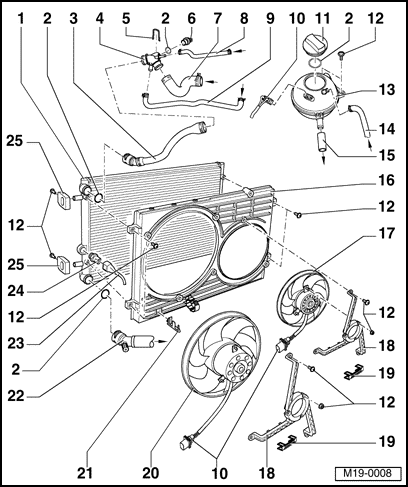
Radiator Fan Diagrams
1 - Radiator
2 - O-ring (Always replace)
3 - Coolant hose, upper
4 - Connector
5 - Retaining clip
6 - A/C Cut-out Thermal Switch -F163-
7 - From connector on cylinder head
8 - From connector on cylinder head/connector
9 - From ATF cooler (Only for vehicles with automatic transmission)
10 - Electrical connector / Color: black
11 - Cap: Test pressure 1.4 to 1.6 bar
12 - Bolt: tighten to 10 Nm (7 ft lb)
13 - Coolant expansion tank
14 - From connector to radiator for EGR/connector
15 - To cylinder head
16 - Fan shroud
17 - Right coolant fan -V35-
18 - Fan bracket
19 - Retaining clip
20 - Coolant fan -V7-
21 - Bracket
22 - Coolant hose, lower
23 - Electrical connector / Black, 3-pin connector
24 - Coolant Fan Control (FC) Thermal Switch -F18-
* Stage 1. 0N: 92 to 97 C
* Stage 1. OFF: 84 to 91 C
* Stage 2. ON: 99 to 105 C
* Stage 2. OFF: 91 to 98 C
25 - Bracket
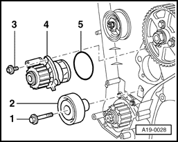
ALH Coolant Water-pump
1. Idler Pully Bolt
2. Idler Pully
3. Pump Housing Bolt
4. Coolant Water-pump
5. O-ring seal
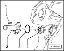
Thermostat 195*F.
1. Mounting Bolt
2. Flange
3. O-ring
4. Thermostat
FYI - For draining G-12 coolant out of the cooling system, open the cooling system drain thumb screw (pictured below).


")