Update
Okay, a bit of an update on a number of things.
Mechanical
First, I installed a used CV joint and an axle flange from a low mileage diesel transmission as I mentioned in the last post. It fit really tight and actually had to be pounded on. That tightened up the assembly. The wave washer and clip fit just fine....pretty easy to install.
Anyway, I went ahead and ordered four new Lobro brand German made CV Joints. For the time being, I put the used tranny oil back in which only has about 3500 miles on it. So, when the new joints come, I will install the other diesel tranny flange and change the oil at that time. Even though my tranny was very clean, the oil came out somewhat dark but with a green hue to it. I guess the new 3rd and 4th gears, as well as new bearings, are broke-in by now, thus, explains the discoloration of the oil. I have new GL-5 ready to install.
Electrical (note: the pics below are from gallery files, nothing new)
I've also ordered a new 12 pin connector to replace the "cobbled" mess I did trying to use a connector from the wiring harness (modified FCM assembly and 14-pin connector).
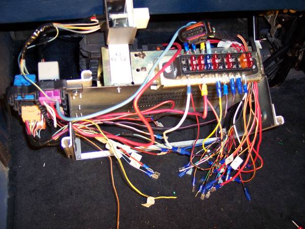
The pic below shows how I used the 14-pin side of a Fan Control Module as a connector. However, I did not use the CAT wire as shown in this pic. But, there are 14 wires soldered to the connector that go to the Blue and Black OEM connectors that are typically located on the Relay panel of the Jetta. The white plastic receiptable side is on the left in pic. You can see in the next pic where the black 14-pin connector plugs into it.
The pic below shows the other side where the 14-pin connector actually plugs into the modified FCM housing. All those wiring splices are okay.
In the pic below, top left, you can see how it looks now.
The pic below shows how the wires come out of the 14-pin side of the modified FCM assembly. All those circuits go to the Blue and Black connectors for the accelerator and cruise control headed to the ECU.
Anyway,
those circuits involve the accelerator and the cruise control as mentioned above. I have all but ruled out any problems up front with the splices there. So, the issue of defaulting to 1200 RPMs at idle must be in this cobbled up connector.

I can use a 12-pin connector and add a 2-pin to cover those connections.
One other thing I have never experienced previously. Last night and today, I was out test driving and the BRAKE light began to flash but the CEL never came on. After about 15 seconds it quit flashing. I ran VCDS and the only thing that showed up was related to the accelerator which is probably those connections mentioned above. It's possible the wire going to the cluster for the emergency brake grounded....... just not sure!
EDIT: I could splice the wires directly to the wires coming off the Blue and Black connectors. However, those connectors have at least one wire each that goes somewhere else. So, in order to keep it as much 'plug & play' as possible, I need the 14-pin connector (soon to be a 12-pin and 2-pin) ............... now, it's clear as mud, right!