Inside the HPFP

Jesse_Boyer

Veteran Member
Joined
Aug 16, 2007
Location
Sioux Falls, SD
TDI
I'm all out...
From Wikipedia

"Early tappets had rollers to reduce wear from the rotating camshaft,[4] but it was found that the roller pivots wore even faster and also that the small radius of the rollers also tended to accelerate wear on the expensive camshaft. Tappets then developed plain flat ends, although these were slightly radiused as 'mushroom' tappets as a perfectly flat end led to 'slamming' against a steep camshaft face.

To reduce wear from the rotating camshaft, the tappets were usually circular and allowed, or even encouraged, to rotate. This avoided grooves developing from the same point always running on the same point of the camshaft. In a few engines, particularly small V8 engines with little space, the tappets were small and non-rotating"

looks like Bosch missed the ball on this one
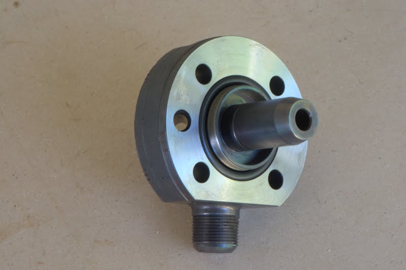
This is how the followers work on ALH (and other) heads/camshaft interfaces. In fact, when the follower STOPS spinning, that's when you're sending the head to Franko6...

Regarding the use of roller lifters, they definitely have their place and work marvelously when designed properly.
 

2004LB7

Veteran Member
Joined
Jun 2, 2013
Location
California
TDI
2006 Jetta
I don't know about the CP3, but the (smaller, similar) CP1 doesn't have flat "followers" as such. The flat pad is only bearing on a ring, the ring runs on an off-centre cam on the shaft. So there's only a very small sliding component as the ring oscillates.
http://www.mefin.ro/poze/commonrail.jpg

edit: that's a BIG image. methinks a link is better...
thanks for fixing that large photo:)

now that i think about it the CP3 doesn't work like a traditional tappet. it is more of a sliding circular motion on the tappet. it has a larger surface area thus less wear.

http://www.youtube.com/watch?v=H-CNXDs9208
 

Jesse_Boyer

Veteran Member
Joined
Aug 16, 2007
Location
Sioux Falls, SD
TDI
I'm all out...
No problem.

Agreed, that's what I alluded to in post #53. I was wrong about the lifter situation. Sweet video; it really sums up the CP3.

I'm not convinced this could all be solved by using a flat tappet-like-device due to the lubricity of ULSA (or , but it's definitely an optional path forward. Someone familiar with materials and machine design might be able to design a new cam as well as a lifter. There's almost no chance of me reading the entire 3+ yearthread where this is being discussed, but I hope someone is pursuing something like this.
 
Last edited:

2004LB7

Veteran Member
Joined
Jun 2, 2013
Location
California
TDI
2006 Jetta
Hay, Jesse

can you measure the black roller holder device thingy's diameter? i thought i measured mine at 25mm but i put it back into my pump.

i was just thinking, because i found a 25mm round disc made out of tungsten carbide on ebay that i was thinking could be pressed in and polished smooth
LB7, I borrowed those pics from various places around the 'net. I have no access to a CP3 or CP4 to give you any measurements.

Sorry :(
Ok, if anyone is interested, i measured the black plug that the roller sits in at 0.9855 inches or 25.0317 mm
 

2004LB7

Veteran Member
Joined
Jun 2, 2013
Location
California
TDI
2006 Jetta
From a casual inspection of this design, based on the amount of contact area between the roller in it's assembly on one side (half of the roller) and to the cam lobe on it's other side (basically just a straight line); it is hard to imagine (practically instead of theoretically) that this roller would spin at all in it's assembly instead of just slipping on the cam lobe.
I here you on this. It seams to me that this minimum contact area creats a high point load that will break down the film strength of the diesel and make physical contact with the cam lobe. Maybe this was intentional in order to creat enough friction to cause it to rotate. And due to the back side of the roller having a larger surface contact area it was meant to "float" on the diesel thus allowing it to rotate.

But if a contaminate gets in there (weather it is a small particle or gasoline, etc) and upsets this balance then the roller stops rolling and instead slides on the cam lobe.
 

Jesse_Boyer

Veteran Member
Joined
Aug 16, 2007
Location
Sioux Falls, SD
TDI
I'm all out...
Keeping this discussion rolling... ;)


No-body-machining concept:
In the stock casting, press in a sleeve that will turn the round bore into an oval. This is also an opportunity to make this sleeve out of the proper material to prevent wear to the AL casting walls. The sleeve could be extruded steel in this type of shape (strikingly similar to the CBS logo)


Next, design a new roller/follower assembly (VERY similar on one end to the very commonly used roller lifter found in typical pushrod engines) to go inside the hole. We'll have to spec a new spring and plunger as this lifter will likely be taller than the current #10 assembly. This not only stops the assembly from spinning, but it will give Crane, Lunati, Comp Cams or any of the big valvetrain manufacturers a chance to incorporate some of their extreme duty lifter technology to the CP4. In extreme cases (high-HP applications,) some cylinder heads are set up with 800lbs on the valve seat closed and upwards of 1200lbs open, maybe more. Those are similar to our forces, if I'm not mistaken.

The roller lifter will have to be matched in material and hardness to the existing camshaft, but I would recommend replacing both as an assembly. If one is significantly harder than the other, you'll have a wear problem again.


Contingency plan:
IF the bore isn't large enough to incorporate a large enough roller lifter, it gets a little more tricky. I would recommend machining the round bore to a slightly oval shape, then pressing in a bearing sleeve that is the same thickness all the way around (similar to the sleeve pressed in for the driven, double lobe camshaft rides on.) Now, design your lifter assembly to be slightly wider, giving more of a footprint on the camshaft lobes, and reducing overall pressure on the lobe and lifter.
 
Last edited:

Jesse_Boyer

Veteran Member
Joined
Aug 16, 2007
Location
Sioux Falls, SD
TDI
I'm all out...
Does anyone have any specific differences of the Passat CP4 vs the Golf/Jetta CP4? What makes this one survive while the previous generation continues to fail? I understand the Passat functions at lower pressures, but is the general construction of this CP4 the same as it's Jetta cousin?
 

2004LB7

Veteran Member
Joined
Jun 2, 2013
Location
California
TDI
2006 Jetta
No-machining concept:
it doesn't seam to completely elimulate machining as the roller assembly will still require some kind of custom machining. but as long as no machining work is needed on the pump body then the parts could be assembled into a kit and easily installed.

i like the thought, as it is very similar to what i was thinking and mentioned earler.
 

2004LB7

Veteran Member
Joined
Jun 2, 2013
Location
California
TDI
2006 Jetta
here is an idea that could be used to eliminate the possibility of the roller assembly turning and would require no permanent modifications to the pump, could be fitted in minutes, etc

the idea is to use the space between the pump head plunger area and the spring and press on a cage like assembly, one half would be on the pump head and the other would be pressed into the inside of the roller assembly.

press one half on here


the other end would be pressed in the roller assembly, of course you wouldn't do it with it still in the pump


this is the idea for the "cage". it does't need to have four prongs, it could have three or two or whatever. the concept would be the same though


this is how it would fit inside


work or not?
 
Last edited:

Jesse_Boyer

Veteran Member
Joined
Aug 16, 2007
Location
Sioux Falls, SD
TDI
I'm all out...
I'd recommend using just two fingers per piece verses 4. They would hold it's position just the same and be less costly, less prone to failure.

Honestly, keeping the orientation of the roller is only half the battle. Even if the #10 assembly rode on the camshaft exactly as designed (never turning 90-deg off proper orientation, there is a wear patter developing on the camshaft. See:


I strongly feel the roller, the receiver it rests within, the receiver coating, and material specifications are subject to review. The fact that the #10 assembly can twist out of proper orientation is only part of the equation. Based on a couple pictures of a camshaft lobe having a slight 'u-shap' like above.
 

2004LB7

Veteran Member
Joined
Jun 2, 2013
Location
California
TDI
2006 Jetta
yah, two "fingers" is likely better

i would think that the cam and roller would last almost indefinitely as long as the roller continued to turn and did not get jammed up with anything. it looks like shaft you posted would mate up perfectly with the roller in the picture in post #55. notice the flat spot on the roller, i bet you that the cam lobe only wore down because the roller stopped turning and slid across the surface instead.
 

Jesse_Boyer

Veteran Member
Joined
Aug 16, 2007
Location
Sioux Falls, SD
TDI
I'm all out...
Looking at the polished shaft posted earlier, there is no u-shape to the lobe surface. The worn u-shape was worn into the cam by the roller. Reason not yet known for sure....


continuing the discussion of the latest path forward:

What is the OD of the protruding cylinder of the attached to the 'head' of the high-pressure side of the pump?

What is the ID of the spring?

Regarding the new piece we'll press into the #10 assembly, the thickness of the base will increase the forces on the roller-to-cam per F = k * x. Increasing load on the cam/roller isn't ideal, I'm guessing.

At risk for coil bind? I don't know the relaxed height of the spring, but we'll need to consider this when designing the piece. Any thickness added will bring the spring closer to coil bind.

Lastly, while we want the piece we press-in to the #10 assembly to stay put, we don't want to deform the body of the #10 assembly. On the other hand, if the new piece somehow shifts within #10 assembly and binds with it's matching 'finger' piece whatsoever, we'll have a massive failure on our hands.

I really need one of these pumps to keep playing with this idea. I'd do a lot better if I had an assembly in front of me to see how much room we have for various options.
 
Last edited:

2004LB7

Veteran Member
Joined
Jun 2, 2013
Location
California
TDI
2006 Jetta
Regarding the new piece we'll press into the #10 assembly, the thickness of the base will increase the forces on the roller-to-cam per F = k * x. Increasing load on the cam/roller isn't ideal, I'm guessing.
designing this part so as to not increase the load on the roller/cam would be easy. the part at the bottom of the spring that pulls the plunger back down with the force of the spring can be eliminated and the base of the new part can do this work

shiny silver piece at the bottom of spring would come out


the new alignment cage would need to have its base made at least close to this parts thickness
 

Jesse_Boyer

Veteran Member
Joined
Aug 16, 2007
Location
Sioux Falls, SD
TDI
I'm all out...
designing this part so as to not increase the load on the roller/cam would be easy. the part at the bottom of the spring that pulls the plunger back down with the force of the spring can be eliminated and the base of the new part can do this work

shiny silver piece at the bottom of spring would come out

the new alignment cage would need to have its base made at least close to this parts thickness
seems feasible. Now it's just a matter of designing the part... and make it relatively easy to manufacture.
 

2004LB7

Veteran Member
Joined
Jun 2, 2013
Location
California
TDI
2006 Jetta
here is some more measurements. "?" = measurements may not be accurate due to not being able to get the micrometer in the space properly.


2004LB7

Veteran Member
Joined
Jun 2, 2013
Location
California
TDI
2006 Jetta
looks like the fingers would have to be made out of 25 gauge steel. thinner then i had hoped. the base can be made out of thicker steel though
 

bassman5066

Veteran Member
Joined
Apr 8, 2011
Location
Honey Brook PA
TDI
2011 Golf 2 Door TDI (sold back for Dieselgate), 91 Golf 4 Door with 1Z swap
seems feasible. Now it's just a matter of designing the part... and make it relatively easy to manufacture.
For prototyping, check out emachineshop.com

I just designed and ordered a T3 adapter flange for my other car from them and its gonna be made from .25 hot rolled steel water jetted into shape. They seem to be able to make anything over there. And there are major quantity discounts too (I.E. 1 of the part I designed will be $75 and 2 will be $82 and 3 will be $85) so if you get past the prototyping phase, production can be scaled up cheaply.

Sent from my XT1080 using Tapatalk
 

Jesse_Boyer

Veteran Member
Joined
Aug 16, 2007
Location
Sioux Falls, SD
TDI
I'm all out...
looks like the fingers would have to be made out of 25 gauge steel. thinner then i had hoped. the base can be made out of thicker steel though
That's the first red flag that came to mind as well. The thickness of the cages is very small. I'm not saying it can't work, but the likelyhood of one of the fingers snagging/catching the spring while in motion is higher than if we used a thicker metal that's less prone to deflection.
 

Jesse_Boyer

Veteran Member
Joined
Aug 16, 2007
Location
Sioux Falls, SD
TDI
I'm all out...
One thing I just thought of is the press-fit of the finger/cage MAY shift over time within it's respective bore (either the head or the #10 assembly.) IE, if they start to walk ever-so-slightly, they may continue to do so. Thus, they're no longer keeping proper alignment between the roller and cam. In fact, they'd be forcing the roller to be in the wrong alignment.
 

Jesse_Boyer

Veteran Member
Joined
Aug 16, 2007
Location
Sioux Falls, SD
TDI
I'm all out...
here is some more measurements. "?" = measurements may not be accurate due to not being able to get the micrometer in the space properly.

looks like the fingers would have to be made out of 25 gauge steel. thinner then i had hoped. the base can be made out of thicker steel though
on the other hand, a super-quick machining operation would take the 0.6060" diameter down a bit and would allow you to use a heavier gauge metal.
 

JFettig

Vendor
Joined
Aug 18, 2010
Location
Blaine, MN
TDI
B5 Passat, 2010 Jetta
Doesn't sound too smart, that gets up to 28,000psi inside there ;)

I don't think you guys are focusing on the right things, it appears to rotate when the pump has basically failed already.
 

2004LB7

Veteran Member
Joined
Jun 2, 2013
Location
California
TDI
2006 Jetta
Doesn't sound too smart, that gets up to 28,000psi inside there ;)
only the top portion of the piston experiences this pressure. the piston only moves up and down about a 1/4 of an inch yet it is over two inches long. the fuel lines are not built as heavy as this part and they hold up fine. agreed this is not the best option as i was trying to avoid having to make any changes to the pump its self but with only a small amount removed it does look like a viable option:)

I don't think you guys are focusing on the right things, it appears to rotate when the pump has basically failed already.
this may be true but how do we know for sure? i think we have two basic issues here, one is the assembly rotating and the roller not turning. if we can guarantee that one wont happen then we can concentrate on solving the other. right now it looks like the easiest problem to tackle is the #10 roller assembly turning in the bore.

personally i have no idea if any of these ideas will work but we got to try something if bosch/VW wont
 

kjclow

Top Post Dawg
Joined
Apr 26, 2003
Location
Charlotte, NC
TDI
2010 JSW TDI silver and black. 2017 Ram Ecodiesel dark red with brown and beige interior.
I remember a few of the earlier failures were the result of the assemby rotating but since VW has been doing the repairs under warranty and not giving the pump back, are we really sure that this is a common route of failure?
 

2004LB7

Veteran Member
Joined
Jun 2, 2013
Location
California
TDI
2006 Jetta
I remember a few of the earlier failures were the result of the assemby rotating but since VW has been doing the repairs under warranty and not giving the pump back, are we really sure that this is a common route of failure?
exactly,

stop the assembly from rotating and see if the pump lasts longer
 

bhutchins

Veteran Member
Joined
Feb 7, 2011
Location
SW Portland OR
TDI
Jetta TDiCup, 02Q built Sept 2010
some more on the side topic of the 4.2 adaption.

development courtesy of 2micron

0.398" thick spacer


CP4.2 mounted on factory bracket with the spacer:


adding a port to the fuel rail
 
Last edited:

2004LB7

Veteran Member
Joined
Jun 2, 2013
Location
California
TDI
2006 Jetta
wouldn't it be better to just use the shaft and front plate from the stock 4.1 HPFP so no adapter plate would be needed?
 

bhutchins

Veteran Member
Joined
Feb 7, 2011
Location
SW Portland OR
TDI
Jetta TDiCup, 02Q built Sept 2010
yes that would be easier unless the one shaft wears out, then you would have to find another doner CP4.1

Vehicles that need a bigger pump are modded with a bigger turbo, maybe Tracking the car and running up to 5000 rpm, which is more strenuous than most cars will see (factory turbofalls flat at 4000 rpm) I'm running the 2micron pure flow and contain kits, so if one pump fails, just replace the pump

so for me, ~$100 for a machined piece of aluminum, is worth having to just install one part.

also, this CP4.2 shaft has a different profile, as seen in page 1 of this thread, similar to if not the same as the passat pump
 
Last edited:

2004LB7

Veteran Member
Joined
Jun 2, 2013
Location
California
TDI
2006 Jetta
all good points, just wondering how much fuel you are trying to get.

with the 4.1 shaft in a 4.2 pump you would theoretically double the fuel quantity available. with the 4.2 shaft you add what? another 20% on top of that?

i know in the Duramax world, running dual CP3's (as i currently do) you have enough fuel to push more then 1000 HP. that is more then three time the factory HP. how does this compare to the CP4.1 in the VWs?
 
Top