[Note: This is split into two posts to get around the 10 image per post limit]
Post #1:
The Motive
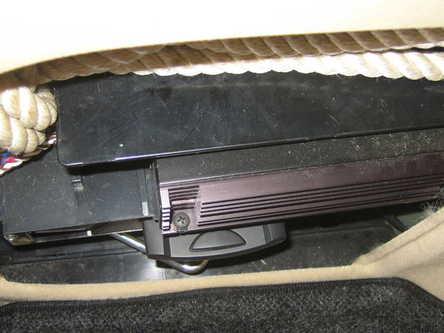
In the Passat Variant, the Phatbox is mounted in the driver's side cargo area cubby, in the space where the CD changer would otherwise go, below the Monsoon amplifier (if so equipped). This is great because the Phatbox is hidden from view, the cable that runs to the headunit is already there, and it makes use of the space. However, with the Phatbox mounted with the regular mounting brackets, the unit is not recessed far enough into the cubby hole, and you will not be able to put the cubby door back on because of the protruding DMS cartridge.
VW/Phatnoise actually does have a documented "fix": cut a hole in the cubby door so that the DMS cartridge can poke through. This obviously leaves the cartridge vulnerable to damage from loads in the cargo area, and also isn't very pretty.
VW Installation Instructions: Phatbox in B5 Wagon/Variant

(Pic courtesy GreystoneSC at Passat World)
There are a few other possible solutions to this problem: some people have cut the aluminum "wings" off the Phatbox heat sink, which makes the unit substantially smaller, and then it can be mounted sideways in the CD changer space, or in the spare wheel well. But, it is possible to mount the unit in the CD changer space without having to modify the cubby door. The key is the Phatbox cable.
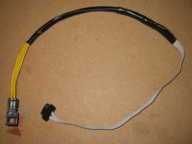
The OE Phatbox cable uses a large connector that adds a couple of inches to the depth of the Phatbox. By manufacturing a new cable to regain those inches, along with a couple of other tweaks, the unit will fit in the space as it should.
Original inspiration for this mod comes from this thread, notably Plutogogo's post #22. The main difference is that I did not want to cut the end off the factory VW cable as Plutogogo did.
The Parts
3M mini-D 26-pin Ribbon Connector: 10126-6000EC
[ 3M 10126-6000EC Product Data Sheet (PDF) ]
Purchase from: Mouser (US$5.20/ea, Mouser p/n: 517-10126-6000EC) or Newark InOne (CDN$7.47/ea, Newark InOne p/n: 52F7593)
I ordered two, just in case I really screwed it up on my first try.

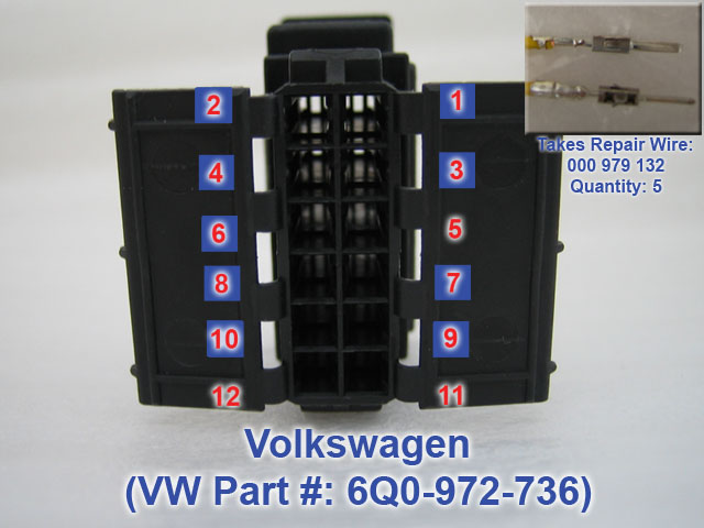
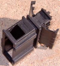
VW OE Phatbox Connector Housing: 6Q0-972-736 (was 3B0-972-736)
Purchase from: Dealer (CDN$2.25)
This connects to the factory headunit harness, the same cable the CD changer would connect to.
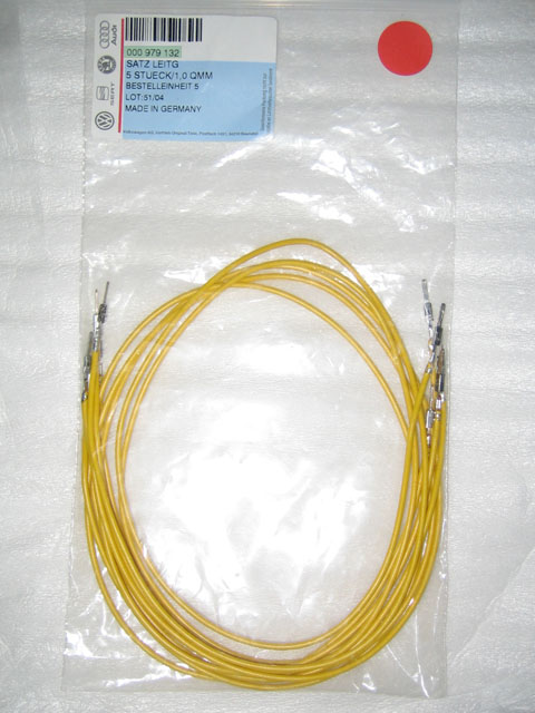
VW Repair Wires: 000-979-132
Quantity: 5 - cut in half for the 9 required terminals
Purchase from: Dealer (CDN$8.15 - *each*!! Find another source for repair wires!)
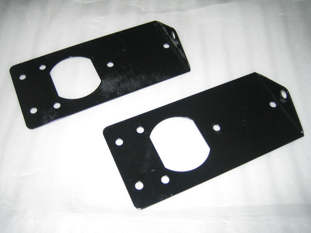
VW Phatbox Mounting Brackets: 1J0-035-234A
Quantity: 2 - left and right sides
Purchase from: Dealer (CDN$8.15/ea)
You will also need bolts to attach the brackets to the Phatbox, and then the Phatbox to the car. You can get bolts from the dealer, but they are easy and cheaper to find at Home Depot or any hardware store with open stock. Minimum 4 bolts, or 6 if you use 2 on each side instead of 1 (as I did). I'm not sure what they are... I had some that fit in my basement hardware collection... Bring the Phatbox with you and see what fits; they don't need to be long, and the shallower the head, the better.
Ribbon Cable: n/a
Purchase from: Nearest geek...
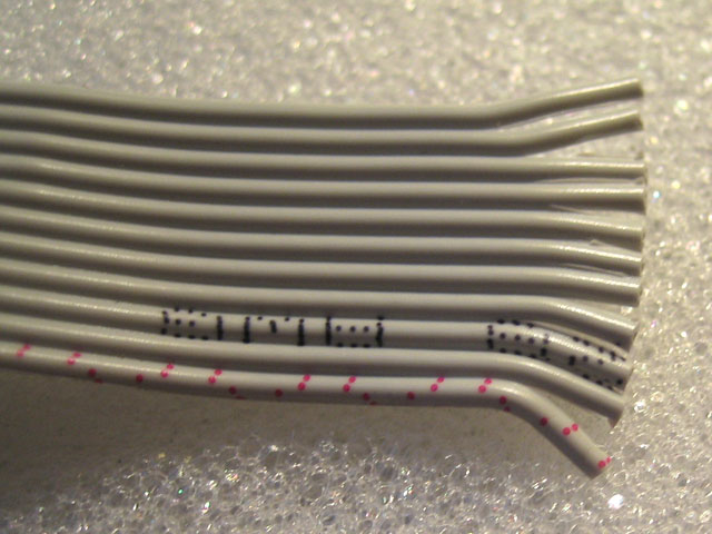
I used IDE (hard drive) ribbon cable, which is readily available from any computer person with a closet. You only need 11 conductors, so just "tear off" what you need. Try to use the side of the cable that has the marked wire (note the red marks on the bottom conductor in the photo below), as it will be easier to keep things straight when you are wiring. A length of 6"-8" is more than sufficient.
The Tools
1. Patience
2. Razor blade, scissors, knife or wire stripper to prep wires
3. Precision soldering iron
4. Heat shrink that will fit the repair wires (or whatever you prefer to isolate & protect the soldered connections)
5. Jewellers screwdriver (flat head)
6. Drill and 3/16" bit
7. Multimeter/circuit tester
8. Electrical tape/loom/conduit (something to reinforce and protect the finished cable)
9. Hacksaw blade
Step 1: Making the Cable
1. Take the 3M connector and insert the small piece with the adhesive backing into the connector. It only fits in one way; make sure you start to peel the backing before inserting it all the way into the connector.
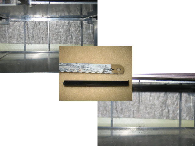
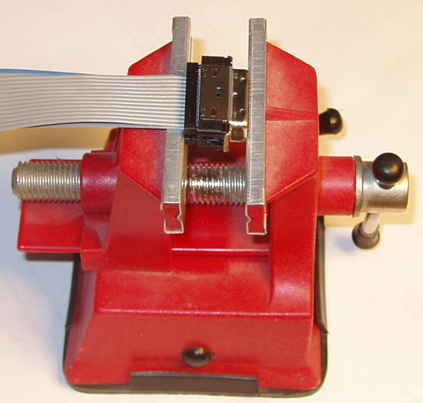
2. Take the ribbon cable, which should have 11 conductors, and separate each cable from its neighbours by just 1/2" or so. As you manipulate the cable, you'll separate some of the wires more so that you can move them, but the objective is to keep it as tight as possible. I used a razor blade to "slice" the cable jacket between each conductor so that I could pull them apart (see photo above).
3. Do the same at the other end of the ribbon cable, although you can probably peel back at least 1". *Carefully* strip 1/2" of the jacket from each conductor. I simply used the edge of a sharp pair of scissors to strip the jacket off - a light pressure is all that's needed.
4. This is the hardest part... Press each conductor into the appropriate pin on the 3M connector. The idea is to have the cable coming into the centre of the connector, and then each conductor will either bend "up" or bend "down" to engage the appropriate location. In this way, you will then lock the connector with the third piece of the 3M package. There is only a very small amount of space to accomplish this, and you may need to separate the conductors further in order to manipulate and seat things properly. Use a small tool to push the conductor down to the bottom of the "V" of each pin. I used a flat head jewellers screwdriver. Be careful not to pierce the conductor jacket with the screwdriver. With the conductors properly seated, they are quite secure.
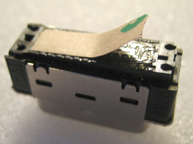
*** NOTE THE ORIENTATION OF THE 3M CONNECTOR!!! ***
There is a small detent on the side of the connector, indicated by the blue arrow in the picture below. Be sure to orient the connector properly before beginning so that you attach the conductors to the proper pins.

*** PAY ATTENTION TO THE NUMBERING!!! ***
Note that the ribbon cable is numbered with the marked conductor as #1. If you do not have a marked conductor, mark it yourself with something PERMANENT before beginning! The red numbers in yellow circles refer to the appropriate pin on the 3M connector for that particular conductor.

I found this sequence to work best for getting the conductors into the connector as neatly as possible. If you alter the sequence MAKE NOTE OF IT and be sure to carry it through to the other end!
4. With all the conductors attached to the pins, use your multimeter/circuit tester to verify each connection. Put one probe on the stripped conductor end, and the other probe into the matching outer contact on the 3M connector. You will need a probe with a fine point to reach the precise contact in the 3M connector. If something doesn't work, fix it...
5. Once all connections have been verified, use the remaining piece of the 3M connector to lock the connections. It can only go on one way. Slide the connector onto the ribbon cable, and press down firmly onto the connector contact pins. It will lock in place quite securely. Whew. Hardest part is done.
Post #1:
The Motive
In the Passat Variant, the Phatbox is mounted in the driver's side cargo area cubby, in the space where the CD changer would otherwise go, below the Monsoon amplifier (if so equipped). This is great because the Phatbox is hidden from view, the cable that runs to the headunit is already there, and it makes use of the space. However, with the Phatbox mounted with the regular mounting brackets, the unit is not recessed far enough into the cubby hole, and you will not be able to put the cubby door back on because of the protruding DMS cartridge.
VW/Phatnoise actually does have a documented "fix": cut a hole in the cubby door so that the DMS cartridge can poke through. This obviously leaves the cartridge vulnerable to damage from loads in the cargo area, and also isn't very pretty.
VW Installation Instructions: Phatbox in B5 Wagon/Variant
(Pic courtesy GreystoneSC at Passat World)
There are a few other possible solutions to this problem: some people have cut the aluminum "wings" off the Phatbox heat sink, which makes the unit substantially smaller, and then it can be mounted sideways in the CD changer space, or in the spare wheel well. But, it is possible to mount the unit in the CD changer space without having to modify the cubby door. The key is the Phatbox cable.
The OE Phatbox cable uses a large connector that adds a couple of inches to the depth of the Phatbox. By manufacturing a new cable to regain those inches, along with a couple of other tweaks, the unit will fit in the space as it should.
Original inspiration for this mod comes from this thread, notably Plutogogo's post #22. The main difference is that I did not want to cut the end off the factory VW cable as Plutogogo did.
The Parts
3M mini-D 26-pin Ribbon Connector: 10126-6000EC
[ 3M 10126-6000EC Product Data Sheet (PDF) ]
Purchase from: Mouser (US$5.20/ea, Mouser p/n: 517-10126-6000EC) or Newark InOne (CDN$7.47/ea, Newark InOne p/n: 52F7593)
I ordered two, just in case I really screwed it up on my first try.
VW OE Phatbox Connector Housing: 6Q0-972-736 (was 3B0-972-736)
Purchase from: Dealer (CDN$2.25)
This connects to the factory headunit harness, the same cable the CD changer would connect to.
VW Repair Wires: 000-979-132
Quantity: 5 - cut in half for the 9 required terminals
Purchase from: Dealer (CDN$8.15 - *each*!! Find another source for repair wires!)
VW Phatbox Mounting Brackets: 1J0-035-234A
Quantity: 2 - left and right sides
Purchase from: Dealer (CDN$8.15/ea)
You will also need bolts to attach the brackets to the Phatbox, and then the Phatbox to the car. You can get bolts from the dealer, but they are easy and cheaper to find at Home Depot or any hardware store with open stock. Minimum 4 bolts, or 6 if you use 2 on each side instead of 1 (as I did). I'm not sure what they are... I had some that fit in my basement hardware collection... Bring the Phatbox with you and see what fits; they don't need to be long, and the shallower the head, the better.
Ribbon Cable: n/a
Purchase from: Nearest geek...
I used IDE (hard drive) ribbon cable, which is readily available from any computer person with a closet. You only need 11 conductors, so just "tear off" what you need. Try to use the side of the cable that has the marked wire (note the red marks on the bottom conductor in the photo below), as it will be easier to keep things straight when you are wiring. A length of 6"-8" is more than sufficient.
The Tools
1. Patience
2. Razor blade, scissors, knife or wire stripper to prep wires
3. Precision soldering iron
4. Heat shrink that will fit the repair wires (or whatever you prefer to isolate & protect the soldered connections)
5. Jewellers screwdriver (flat head)
6. Drill and 3/16" bit
7. Multimeter/circuit tester
8. Electrical tape/loom/conduit (something to reinforce and protect the finished cable)
9. Hacksaw blade
Step 1: Making the Cable
1. Take the 3M connector and insert the small piece with the adhesive backing into the connector. It only fits in one way; make sure you start to peel the backing before inserting it all the way into the connector.
2. Take the ribbon cable, which should have 11 conductors, and separate each cable from its neighbours by just 1/2" or so. As you manipulate the cable, you'll separate some of the wires more so that you can move them, but the objective is to keep it as tight as possible. I used a razor blade to "slice" the cable jacket between each conductor so that I could pull them apart (see photo above).
3. Do the same at the other end of the ribbon cable, although you can probably peel back at least 1". *Carefully* strip 1/2" of the jacket from each conductor. I simply used the edge of a sharp pair of scissors to strip the jacket off - a light pressure is all that's needed.
4. This is the hardest part... Press each conductor into the appropriate pin on the 3M connector. The idea is to have the cable coming into the centre of the connector, and then each conductor will either bend "up" or bend "down" to engage the appropriate location. In this way, you will then lock the connector with the third piece of the 3M package. There is only a very small amount of space to accomplish this, and you may need to separate the conductors further in order to manipulate and seat things properly. Use a small tool to push the conductor down to the bottom of the "V" of each pin. I used a flat head jewellers screwdriver. Be careful not to pierce the conductor jacket with the screwdriver. With the conductors properly seated, they are quite secure.
*** NOTE THE ORIENTATION OF THE 3M CONNECTOR!!! ***
There is a small detent on the side of the connector, indicated by the blue arrow in the picture below. Be sure to orient the connector properly before beginning so that you attach the conductors to the proper pins.
*** PAY ATTENTION TO THE NUMBERING!!! ***
Note that the ribbon cable is numbered with the marked conductor as #1. If you do not have a marked conductor, mark it yourself with something PERMANENT before beginning! The red numbers in yellow circles refer to the appropriate pin on the 3M connector for that particular conductor.
I found this sequence to work best for getting the conductors into the connector as neatly as possible. If you alter the sequence MAKE NOTE OF IT and be sure to carry it through to the other end!
Code:
Conductor  3M Connector
1 --------- 13
2 --------- 12
3 --------- 10
4 --------- 25
5 --------- 24
6 --------- 4
7 --------- 3
8 --------- 2
9 --------- 1
10 -------- 16
11 -------- 145. Once all connections have been verified, use the remaining piece of the 3M connector to lock the connections. It can only go on one way. Slide the connector onto the ribbon cable, and press down firmly onto the connector contact pins. It will lock in place quite securely. Whew. Hardest part is done.