AndyBees
Top Post Dawg
- Joined
- May 27, 2003
- Location
- Southeast Kentucky
- TDI
- Silver 2003 Jetta TDI, Silver 2000 Jetta TDI (sold), '84 Vanagon with '02 ALH engine
This is a continuation of the Fuel Level Sending Unit & Sensor Mod:
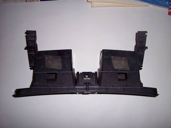
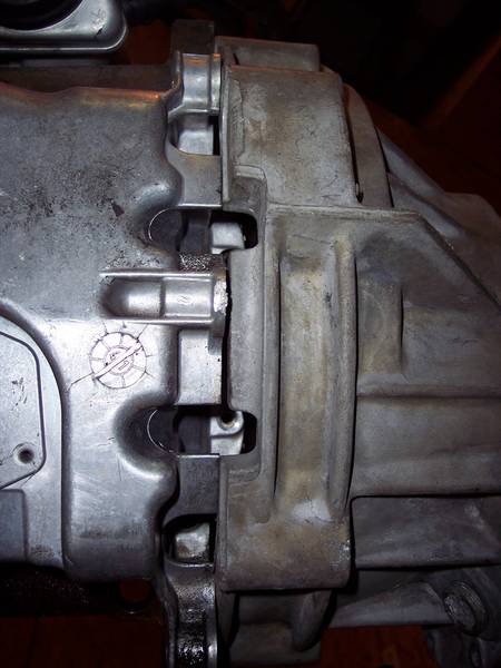
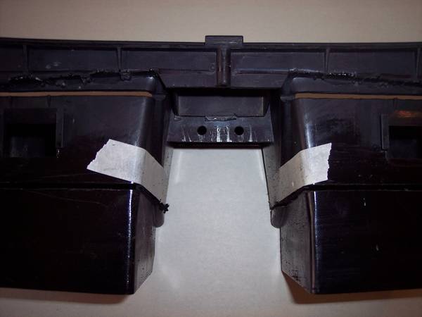
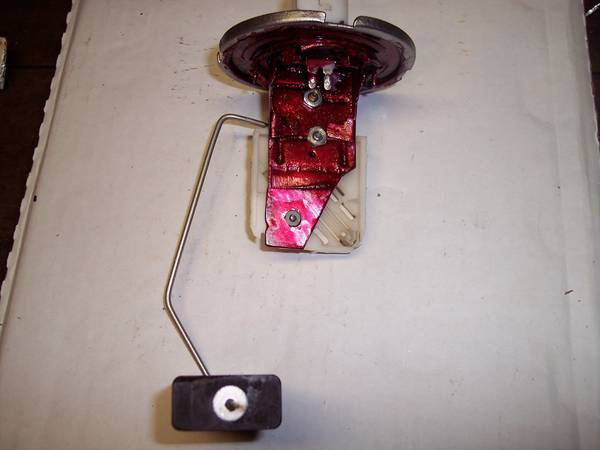
11. This is a view of the ALH potentimeter attached to the modified Vanagon Fuel Level Sending Unit. Notice the small bolts I used to assemble the various parts. As mentioned later, these parts were given a "dab" of Red-Kote to prevent damage from corrision:

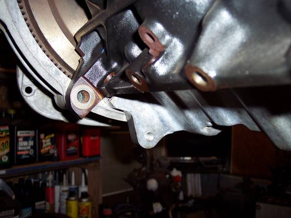
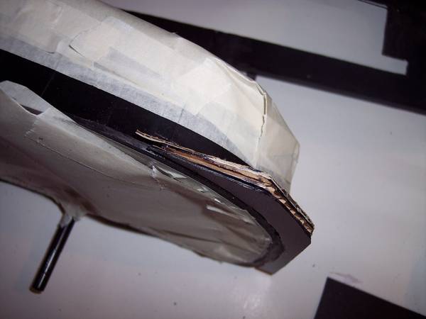
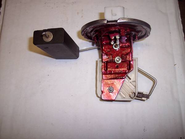
12. This is another view of the modified unit.....roughly in the "empty tank" position:

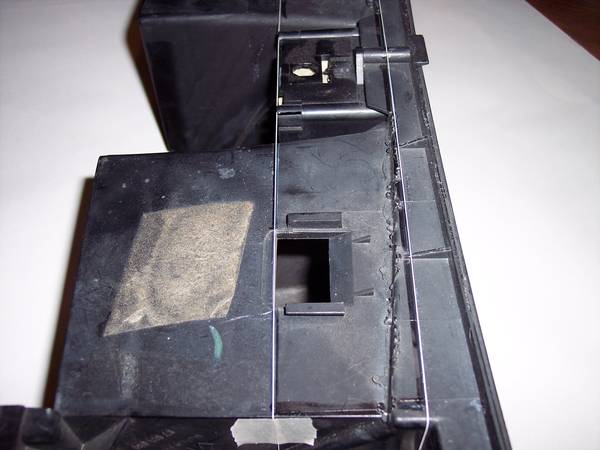
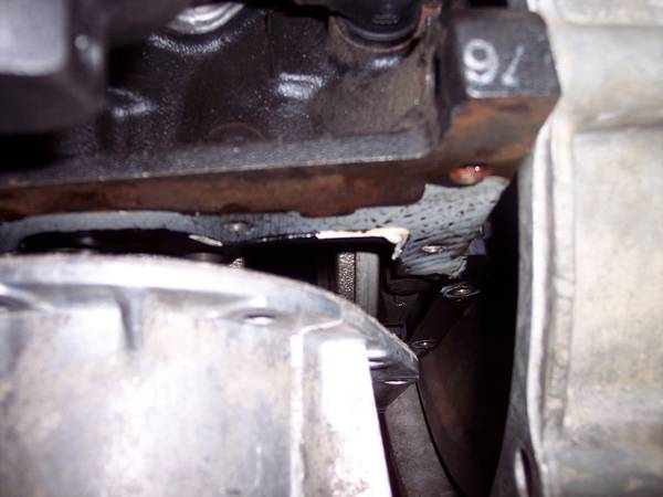
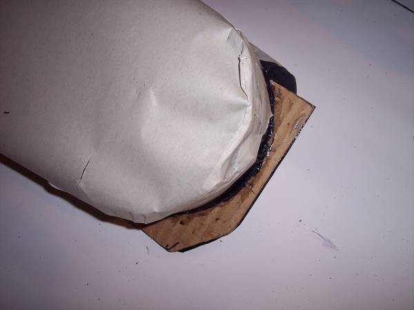
13. This is a view from the other side. In this view, you can see that I added an extension on the modified Vanagon Unit. I also bored a hole near the bottom if the extension. That hole has the plastic pivet point of the potentimeter from the ALH unit in it. Look close and you can see the end of the Float wire. Notice that the ALH Potentimeter is not "exactly" square with the Vanagon unit. It is slightly off square. That angle puts the float higher at the full position and keeps it a little more off the bottom at the empty position:
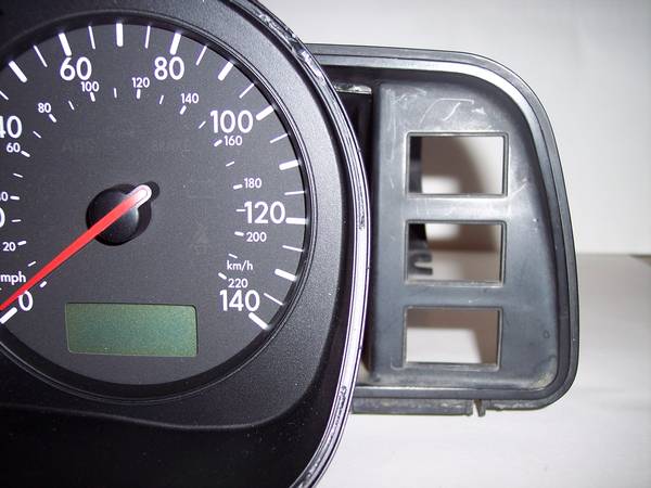
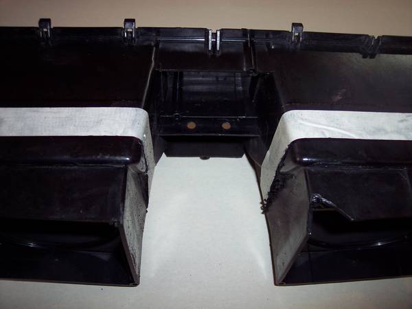
14. This view shows the Sensor wires in place. They are soldered on the Connector but are Clipped on the Potentimeter. I did not shorten the wires. The extra length was helpful with installation. It was impossible to install the Unit with it bolted together. Thus, working with various tools, I put the float part inside the tank first. Then I carefully bolted the two parts together and added Red-Kote to the bolt heads and nuts. Then, I plugged the sensor wires in place.....they are not crossed. (smile). Also, they were bent in a fashion to avoid contact with the float or float wire:
15. This is another view showing the wires:
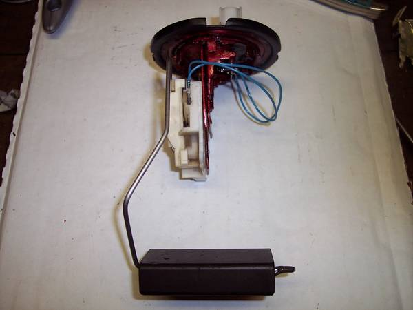
16. This is a similar view as above. However, notice, the ALH Potentimeter is "off-set" from the modified Vanagon unit compared to the above photo. The off-set is necessary to allow the float to move thru the full sweep of the potentimeter. It is about 5/16 inch off the bottom at "empty." The first attempts I determined the float was hanging on an edge inside the tank which did not allow the Potentimeter to complete a full swing to the empty position.

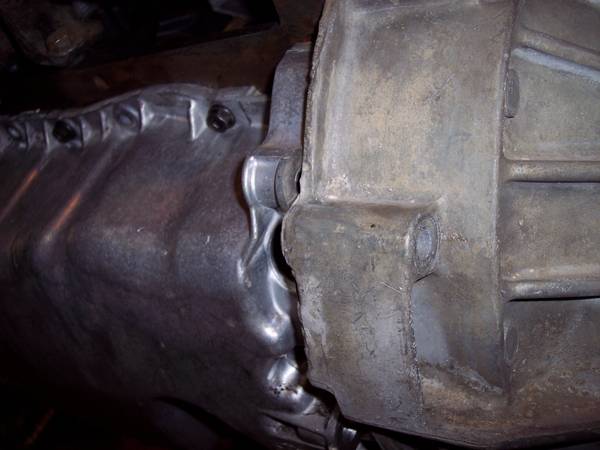
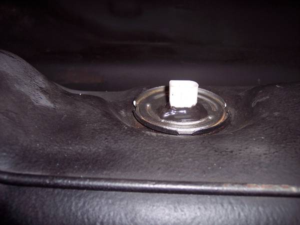
17. This is a view of the MODIFIED unit installed in the Vanagon Fuel Tank:
EDIT: I have since cut the plastic away on this connector and soldered long pig-tail wires directly to the connection. The reason I did this is because the connector/plug was up fairly tight against the bottom of the Van flooring (sorry, no photos but it is a fairly straight forward procedure). I did cover the soldered connections with JB Weld.

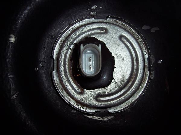
18. Another view of the installed unit:
19. And, here is the final photo of the unit installed in the tank:
Keep in mind, I took far more photos than what's posted here. And, since I only have two hands, I did not take photos of the actual installation process. It was actually installed in two pieces which were bolted (small bolts) and coated with Red-Kote before lowering into place. Although not shown in any of the photos, I did use the large rubber O-ring for sealing the unit head.
Also, there were several trial and error efforts to get it right. The float wire "bends" cannot be given justice with these photos. The tank will probably hold two or more gallons after showing full on the gauge. It will be near empty when the Buzzer goes off!
Due to the very long sweep of the ALH Potentimeter, it was all but impossible to bend the float wire in a manner that accurately reflects both FULL and EMPTY. Actually, I believe due to the Fuel Tank configuration, it would not be possible to bend the float wire in a fashion to show Full without empty being reflected with almost a half tank of fuel. It was a give and take task! Hopefully, it will serve the purpose square in the middle of the Ball Park.......smile!
The Fuel Tank is not ready for the final coat of paint (Truck Bed liner).
Okay, hope this is informative to all who reads!
11. This is a view of the ALH potentimeter attached to the modified Vanagon Fuel Level Sending Unit. Notice the small bolts I used to assemble the various parts. As mentioned later, these parts were given a "dab" of Red-Kote to prevent damage from corrision:
12. This is another view of the modified unit.....roughly in the "empty tank" position:
13. This is a view from the other side. In this view, you can see that I added an extension on the modified Vanagon Unit. I also bored a hole near the bottom if the extension. That hole has the plastic pivet point of the potentimeter from the ALH unit in it. Look close and you can see the end of the Float wire. Notice that the ALH Potentimeter is not "exactly" square with the Vanagon unit. It is slightly off square. That angle puts the float higher at the full position and keeps it a little more off the bottom at the empty position:
14. This view shows the Sensor wires in place. They are soldered on the Connector but are Clipped on the Potentimeter. I did not shorten the wires. The extra length was helpful with installation. It was impossible to install the Unit with it bolted together. Thus, working with various tools, I put the float part inside the tank first. Then I carefully bolted the two parts together and added Red-Kote to the bolt heads and nuts. Then, I plugged the sensor wires in place.....they are not crossed. (smile). Also, they were bent in a fashion to avoid contact with the float or float wire:
15. This is another view showing the wires:
16. This is a similar view as above. However, notice, the ALH Potentimeter is "off-set" from the modified Vanagon unit compared to the above photo. The off-set is necessary to allow the float to move thru the full sweep of the potentimeter. It is about 5/16 inch off the bottom at "empty." The first attempts I determined the float was hanging on an edge inside the tank which did not allow the Potentimeter to complete a full swing to the empty position.
17. This is a view of the MODIFIED unit installed in the Vanagon Fuel Tank:
EDIT: I have since cut the plastic away on this connector and soldered long pig-tail wires directly to the connection. The reason I did this is because the connector/plug was up fairly tight against the bottom of the Van flooring (sorry, no photos but it is a fairly straight forward procedure). I did cover the soldered connections with JB Weld.
18. Another view of the installed unit:
19. And, here is the final photo of the unit installed in the tank:
Keep in mind, I took far more photos than what's posted here. And, since I only have two hands, I did not take photos of the actual installation process. It was actually installed in two pieces which were bolted (small bolts) and coated with Red-Kote before lowering into place. Although not shown in any of the photos, I did use the large rubber O-ring for sealing the unit head.
Also, there were several trial and error efforts to get it right. The float wire "bends" cannot be given justice with these photos. The tank will probably hold two or more gallons after showing full on the gauge. It will be near empty when the Buzzer goes off!
Due to the very long sweep of the ALH Potentimeter, it was all but impossible to bend the float wire in a manner that accurately reflects both FULL and EMPTY. Actually, I believe due to the Fuel Tank configuration, it would not be possible to bend the float wire in a fashion to show Full without empty being reflected with almost a half tank of fuel. It was a give and take task! Hopefully, it will serve the purpose square in the middle of the Ball Park.......smile!
The Fuel Tank is not ready for the final coat of paint (Truck Bed liner).
Okay, hope this is informative to all who reads!
Last edited:
")