Update
These photos are a follow-up to the last update.
Comments are at the top of the photos.
Here I try to show the relative position of a few circuits and how they will look in reality!
Notice the five colored connectors (White, Black, Brown, Blue and Orange). I could cut them off and splice each wire individually. However, the connectors provide a reference in the event a problem should show it's ugly face sometime in the future.
This photo shows the "wiring mess" as it obviously appears to be.
Notice the one 53 Relay. There will be another one just below it. They are for the Coolant GPs.
See the 109 Relay. The Blue Connector is associated with it. The Blue Connector primarily contains the Accelerator circuit!
At the bottom of the photo you can see the one red power wire coming out of the Main Fuse box. It goes to the 109 Relay. The Blue wire comes out of the 109 Relay and goes to the Fuse Panel and will be spliced for three of the fuses (per the Schematics in Bentley)
At the top of the photo is the Glow Plug Relay. Also, the "unwrapped" wires all go to the five colored connectors and the two 53 Relays. I will wrap those wires for easy work and neatness!
In this photo, you can see the colored connectors a little better. The black one is between the white and blue connector (sorry about the focus). Also, the large red wires will be "cut to fit" and installed in the Main Fuse Box per the Schematics in the Bentley.
This is a closer view of Relay 109. Notice the small blue and yellow wire. It comes off the 109 Relay connector and goes "into" the bundle coming off the Blue Connector. The circuit goes back to the Blue Connector to Pin T10h/8 and from there the circuit goes to T121/18 on the ECU .........so, switching on the ignition key activates the 109 Relay as opposed to the other way around.
Also, as stated above, the circuits coming out of the Blue Connector go to the Accelerator at the front of the vehicle. These wires will all be cut and spliced for length as necesssary.
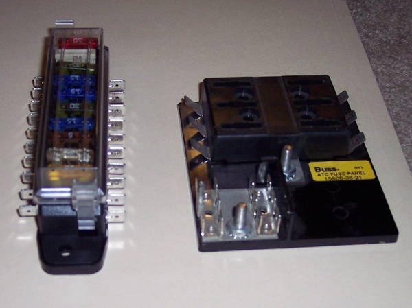
In this pic, you can better see the larger red wires. As previously stated, they will be cut to fit and installed in the black box (Main Fuse Box). Also, there will be a large hot wire from the Starter (yes, Starter) to power the Main Fuse Box. On the Vanagon starter, the main terminal at the Solonoid will receive the ALT Wire and the Big Battery wire, thus the source of power for the Main Fuse Box.
Also, notice the Black connector (with white paint on it) on the Main Fuse Box. There are three circuits there, of which one, normally provides power to the Fan Control Module for the fans and the other two were used for the ABS. Well, I am using them for Fuses 12, 13, and 15 (OBD 16, F47/1[brake switch] & T32/23 [+positive for the Cluster]). Remember, using these three Fuses eliminates the other Aftermarket fuse panel.
Another view of the Relay panel with the Colored Circuit Connectors. The Panel does not hold the conncectors tight enough for "plug-in" purposes. However, they will stay in place once connected. I did consider using epoxy to permenantly secure them, but decided against that idea. I want this thing to stay "plug and play." So, if I need to remove the central mounting unit it will not be a hassle!
Here in this photo is a close-up of the Blue wire coming off the 109 Relay. As previously stated, it will be cut and spliced to provide power to Fuses 32, 34 & 42 (per the schematics in the Bentley).
These three circuits power up the following:
Fuse 32 - At/on the IP, G81, G149, N146 and T121/1 & T121/2 to the ECU
Fuse 34 - N108, G70, N75, N18, & N239
Fuse 43 - F36, F47, N79 and J359 & J360
Now ...........do you better understand the IMPORTANCE of the 109 Relay!
In this pic, you can see the main connectors to the ECU. Also, you can see my finger is on the wire bundle from the Blue Connector which goes to the Accelerator.
This is a closer shot of the Glow Plug Relay. I will fabricate a mounting bracket about where it is laying there.
Of course, the above photos are of the Unit laying on the work bench. However, I do believe working with it in place under the back seat will be quite easy!
Comments welcome, as well as questions.
EDIT: I should make it clear, the wiring bundle for each connector to the ECU has been modified somewhat. I opened them up (unwraped the factory tape) to locate some of the wiring for various branches. I then cut and spliced selected wires giving more length so I could relocate the "branch" in another spot on the bundle. Then, I re-wrapped each bundle with good electrical tape.
At this point, the Wiring all begins to fall in place and I'm beginning to better understand how it will look. I've been thru all the circuits on paper numerous times, checking and re-checking. Looking at it as it begins to take shape brings everything into perspective .....yes, believe me, all those nights until 3:00 in the morning are beginning to pay off!