dunno how relevent it is as my vnt is vacuum but I tune rover diesels and there is no vnt solution so i've been having to build my own.
Unfortunately I'm not a fan of arduino, nor did I even know it existed at the time, so I had to go the long route of learning electronics, coding and so forth. Even had to design my own pcb's

result is it looks a bit rough -
haven't finished the software but this was an artists impression:
Eventually after a hefty amount of time i've started to see results:
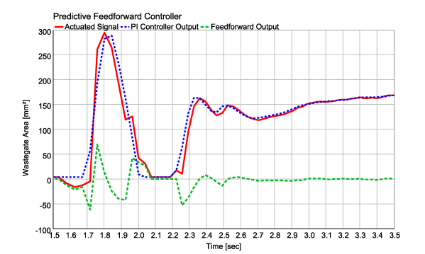
Green line is requested (i intend this to be mappable to either quantity adjuster feedback line or tps so you can base target boost on load) though on that test it was set static. Blue line is actual boost, red line is an unused channel (I sometimes use it to report duty cycle back to laptop so i can check its working).
It uses a very simple mainly proportional control loop though im still working on the control engine. The units are in byte value (i.e what the controller computer sees) rather than real world values i'm afraid so it might not make much sense to you.
here's another log with duty logging enabled:
Not sure if this is of any interest to anyone, but this vnt control has been my 'baby' for about a year now, it's been slow going and i've had more failure than success, but it's getting there. All configs are held in eeprom so technically once my protocols finished it's 'mappable'.
My main aim now is to try and dampen the duty cycle response.
I have wondered how difficult it would be to make it work with an electronic actuator - pwm wouldn't be too bad i dont think, CAN would be harder but some microprocessors i use do have can support so you couldn't rule it out i guess, though it'd need new schematic.